Introduction
Mastering the Bar Bending Schedule is one of the most critical skills for site engineers, quantity surveyors, and project managers. In reinforced concrete structures, steel reinforcement provides the necessary tensile strength to balance the compressive strength of concrete.
However, steel is one of the most expensive materials on a construction site. Improper estimation, incorrect cutting lengths, and poor management can lead to massive material wastage, budget overruns, and structural safety hazards.
This comprehensive guide breaks down everything you need to know about the Bar Bending Schedule. It includes core mathematical formulas, step-by-step practical site examples, unit conversion tables, and advanced quality control methodologies.
What is a Bar Bending Schedule?
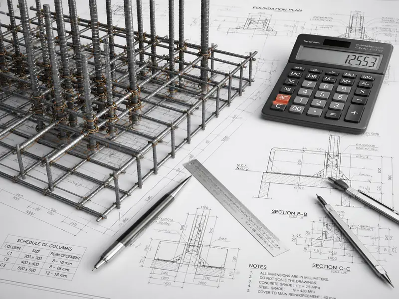
A Bar Bending Schedule, commonly abbreviated as BBS, is a structural document that provides details of reinforcement steel for a given structural element. It lists the location, mark, type, size, number, cutting length, bending details, and total weight of the steel bars required for a construction member like a footing, beam, column, or slab.
Why is BBS Essential on a Construction Site?
- Accurate Procurement: It provides an exact estimation of the steel required for different phases of the project, preventing under-ordering or over-ordering.
- Minimises Wastage: By planning cutting lengths systematically, engineers can combine bar lengths to minimise scrap steel.
- Speeds Up Construction: Steel fixers at the cutting yard can pre-cut and bend bars according to the schedule before transporting them to the execution deck.
- Quality and Compliance: It ensures the reinforcement matches the design requirements, clear covers, and standard hooks specified by design codes like IS 2502, BS 8666, or ACI 318.
- Better Billing and Auditing: Acts as a transparent document for checking contractor bills and conducting material audits.
Standard Rebar Diameters and Unit Weights
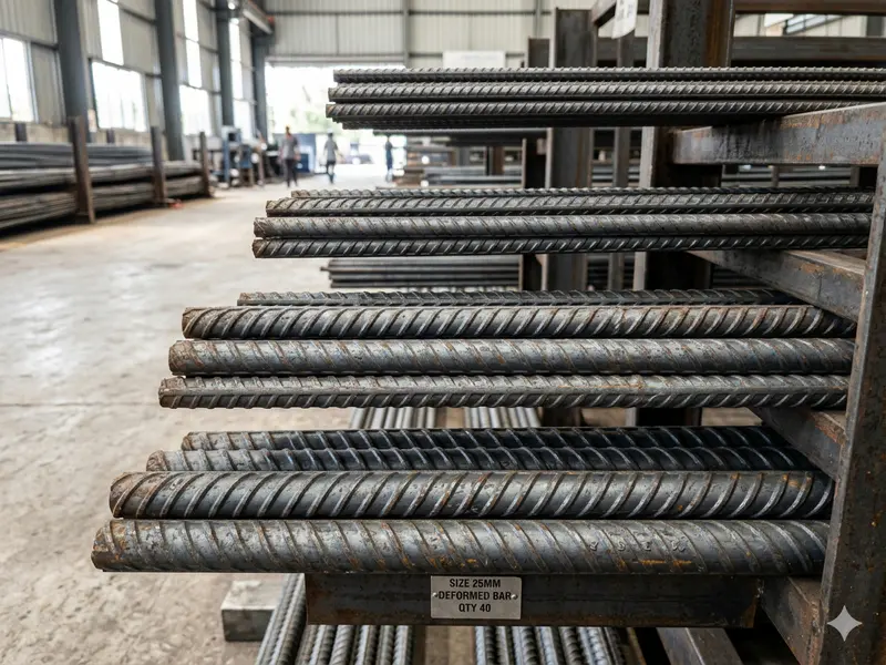
Reinforcement steel is manufactured in standard lengths (usually 12 metres or 40 feet) and specific diameters. To calculate the total weight of steel, engineers use a definitive unit weight formula.
The Standard Weight Formula
The weight of a steel bar per metre length is calculated using the following formula:
- Weight per Metre (kg/m) = (D x D) / 162
- Where D = Diameter of the bar in millimetres (mm)
For feet/pounds measurement systems, the formula is:
- Weight per Foot (lb/ft) = (D x D) / 533
- Where D = Diameter of the bar in eighths of an inch (standard US bar sizes)
Standard Steel Weights Table
| Bar Diameter (mm) | Weight per Metre (kg/m) | Weight per Standard 12m Bar (kg) |
|---|---|---|
| 6 mm | 0.222 kg/m | 2.66 kg |
| 8 mm | 0.395 kg/m | 4.74 kg |
| 10 mm | 0.617 kg/m | 7.40 kg |
| 12 mm | 0.888 kg/m | 10.66 kg |
| 16 mm | 1.578 kg/m | 18.94 kg |
| 20 mm | 2.466 kg/m | 29.59 kg |
| 25 mm | 3.853 kg/m | 46.24 kg |
| 32 mm | 6.313 kg/m | 75.76 kg |
| 40 mm | 9.865 kg/m | 118.38 kg |
👉 Read also: Steel Weight Calculation Formula in Civil Engineering
Core Mathematical Formulas for BBS
To build a flawless Bar Bending Schedule, you must master three main types of calculations: Clear Cover adjustments, Hook Allowances, and Bend Deductions.
1. Concrete Clear Cover Standards
Clear cover is the distance between the outer surface of the concrete element and the outermost surface of the reinforcement. It protects steel bars from corrosion, weathering, and fire damage.
- Footings / Foundations: 50 mm to 75 mm
- Columns: 40 mm
- Beams: 25 mm to 30 mm
- Slabs: 15 mm to 20 mm
- Retaining Walls: 20 mm to 25 mm
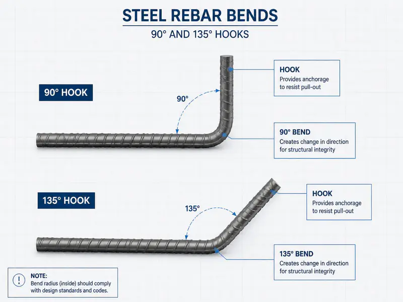
2. Hook Allowances and Crank Lengths
Standard hooks are added to bars (especially in stirrups, ties, and tensile zones) to provide proper anchorage inside the concrete block.
- Standard 90-degree Hook Length: 10 x D (or minimum 75 mm)
- Standard 135-degree Hook Length: 10 x D or 12 x D (commonly used for earthquake-resistant stirrups)
- Standard 180-degree Hook Length: 9 x D
- Crank (Bent-up) Bar Additional Length: 0.42 x H
- Where H = Total depth of slab/beam minus top cover, bottom cover, and diameter of the bar.
3. Bend Deduction Rules
When steel bars are bent around a mandrel on site, the outer fibres of the steel stretch, causing an elongation in length. If you do not deduct this extra length from your calculations, the cut bar will turn out slightly longer than required, conflicting with concrete clear covers.
- For a 45-degree bend: Deduct 1 x D
- For a 90-degree bend: Deduct 2 x D
- For a 135-degree bend: Deduct 3 x D
- For a 180-degree bend: Deduct 4 x D
- Where D = Diameter of the bar.
Step-by-Step Practical BBS Examples
Let us apply these formulas to common on-site reinforcement scenarios.
Example 1: Bar Bending Schedule for a Beam Stirrup

Problem Scenario: Find the cutting length of an 8 mm diameter rectangular stirrup for a beam with dimensions 300 mm x 450 mm. The clear cover for the beam is 25 mm. The stirrup has two 135-degree hooks.
Step 1: Calculate the Dimensions of the Inner Stirrup (A and B)
- Width of Stirrup (A) = Total Width – (2 x Clear Cover) – (2 x Half Stirrup Diameter)
- To keep it standard on-site: Width (A) = 300 – (2 x 25) = 250 mm
- Height of Stirrup (B) = Total Height – (2 x Clear Cover)
- Height (B) = 450 – (2 x 25) = 400 mm
Step 2: Determine Hook Lengths
- For a 135-degree hook, the standard length is 10 x D.
- Total Hook Length = 2 x (10 x 8 mm) = 160 mm
Step 3: Calculate Bend Deductions
- The rectangular stirrup has three 90-degree bends and two 135-degree bends.
- Deduction for 90-degree bends = 3 x (2 x D) = 3 x 2 x 8 = 48 mm
- Deduction for 135-degree bends = 2 x (3 x D) = 2 x 3 x 8 = 48 mm
- Total Bend Deduction = 48 + 48 = 96 mm
Step 4: Final Cutting Length Calculation
- Cutting Length = (2 x A) + (2 x B) + Total Hook Length – Total Bend Deduction
- Cutting Length = (2 x 250) + (2 x 400) + 160 – 96
- Cutting Length = 500 + 800 + 160 – 96 = 1364 mm or 1.364 metres
Example 2: Bar Bending Schedule for a Concrete Footing
Problem Scenario: A square isolated footing has dimensions 1500 mm x 1500 mm with a depth of 400 mm. It requires a mesh of 12 mm diameter bars spaced at 150 mm centre-to-centre in both directions. The clear cover for the foundation is 50 mm. The ends of the bars are bent upward into 90-degree hooks of 100 mm height.
Step 1: Calculate the Number of Bars Required
- Length of footing available for spacing = 1500 – (2 x Clear Cover) = 1500 – (2 x 50) = 1400 mm
- Number of Bars = (Available Length / Spacing) + 1
- Number of Bars = (1400 / 150) + 1 = 9.33 + 1 = 10.33 -> Round up to 11 bars
- Since it is a square footing, 11 bars are required for the X-direction and 11 bars for the Y-direction. Total bars = 22.
Step 2: Calculate the Cutting Length of a Single Bar
- Horizontal Length = Total Footing Width – (2 x Clear Cover) = 1500 – (2 x 50) = 1400 mm
- Vertical Hook Lengths = 2 x 100 mm = 200 mm
- Bend Deductions = Two 90-degree bends = 2 x (2 x D) = 2 x 2 x 12 = 48 mm
- Cutting Length = Horizontal Length + Hook Lengths – Bend Deductions
- Cutting Length = 1400 + 200 – 48 = 1552 mm or 1.552 metres
Step 3: Total Weight of Steel for Footing
- Total Length of 12mm bar = 22 bars x 1.552 metres = 34.144 metres
- Unit Weight of 12mm bar = (12 x 12) / 162 = 0.888 kg/m
- Total Weight = 34.144 m x 0.888 kg/m = 30.32 kg
Unit Conversions and Quantities in Civil Engineering
On massive infrastructure projects, billing departments, logistics companies, and commercial suppliers track materials using multiple units. Slabs are estimated in volume, but steel is purchased in weight.
Here are the essential conversion factors you must keep handy on-site.
Volume to Weight Structural Conversions
- 1 Cubic Metre (cum) of Reinforced Concrete weighs roughly 2400 kg to 2500 kg.
- Average Steel Consumption Rule of Thumb:
- Slabs: 80 kg to 100 kg per cubic metre of concrete.
- Beams: 100 kg to 130 kg per cubic metre of concrete.
- Columns: 120 kg to 160 kg per cubic metre of concrete.
- Footings: 70 kg to 90 kg per cubic metre of concrete.
Standard Unit Conversion Table
| Convert From | Convert To | Multiply By |
|---|---|---|
| Cubic Metres (cum) | Cubic Feet (CFT) | 35.3147 |
| Cubic Metres (cum) | Brass (Common in India) | 0.3531 (1 Brass = 100 CFT) |
| Metric Tons | Kilograms (kg) | 1000 |
| Metric Tons | Pounds (lbs) | 2204.62 |
| Quintals | Kilograms (kg) | 100 |
| Metres | Feet | 3.2808 |
| Inches | Millimetres (mm) | 25.4 |
Site Quality Control, Engineering Rules, and Wastage Management
An expert engineer differentiates themselves by how effectively they manage quality and handle material wastage on the ground.
On-Site Rebar Quality Checks
Before you approve steel bars for bending according to your schedule, conduct these essential physical checks:
- The Bend and Re-bend Test: Bend a sample bar to 180 degrees. Look closely for cracks or fractures on the outside tension zone. For re-bend tests, bend it to 45 degrees, submerge it in boiling water for 30 minutes, and bend it back. No signs of structural tearing should appear.
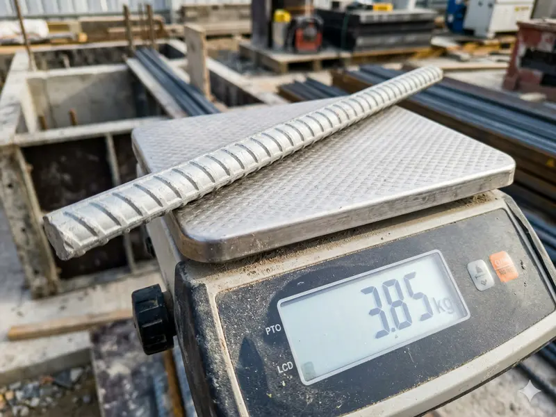
- Nominal Mass Verification: Cut exactly 1 metre of a sample bar using a hacksaw. Weigh it on a calibrated electronic scale. Compare it with the theoretical standard weights listed in the Bar Bending Schedule formula. A variation within +/- 4% to 7% (depending on diameter) is acceptable under standard codes.
- Surface Condition Check: Ensure the bars are free from loose mill scale, thick rust pitting, oil, mud, or paint coats, which degrade the mechanical bond between concrete and steel.
Lap Splice Length Rules
Since standard manufactured bars are only 12 metres long, structural elements longer than 12 metres require bars to be overlapped.
- Tension Lapping Length: Usually 50 x D (commonly applied in beams and slabs)
- Compression Lapping Length: Usually 40 x D (commonly applied in columns)
- Staggering Rule: Never locate all lap joints at the same cross-section line. Stagger them by at least 1.3 times the lap length to avoid creating localised failure zones.
Controlling Steel Wastage
Wastage factors normally range between 3% to 5% on well-managed construction sites. To prevent this figure from escalating:
- Use Scrap Management Software: Map out leftover cut-pieces (e.g., 2m, 3m pieces) and check if they can be reused for short stirrup extensions, spacer bars, or lintel beams.
- Optimise Order Lengths: If a project requires thousands of 4.5-metre column bars, standard 12-metre bars will yield a 3-metre waste piece per bar. Coordinate with manufacturing plants to deliver customised lengths for high-volume orders.
Frequently Asked Questions (FAQs)
1. What is the difference between Nominal Cover and Clear Cover?
Clear Cover is the distance from the outermost surface of the concrete to the outermost surface of the steel reinforcement (usually the stirrup). Nominal Cover is the term used by modern design codes (like IS 456) to specify the clear cover design values based on exposure conditions to weather and soil.
2. Why do we deduct length for bends in a Bar Bending Schedule?
When a steel bar is bent, its centerline length remains constant, but the outer face stretches out due to tensile forces. If you do not perform bend deductions during estimation, the cut bars will exceed the structural perimeter, resulting in bars breaking through the exterior concrete faces or leaving zero clear cover.
3. What are spacer bars, and are they counted in BBS?
Spacer bars (or pin bars) are short pieces of steel placed between two layers of reinforcement grids (such as in deep beams or double-mesh slabs) to maintain vertical separation. Yes, they must be estimated, added to the BBS, and factored into the final project cost calculations.
4. How do I calculate the weight of steel if the diameter is given in inches?
Convert the inch fraction to millimetres (1 inch = 25.4 mm) and use the standard formula (D x D) / 162. Alternatively, use the US imperial standard formula: Weight per Foot (lb/ft) = (Bar Size number squared) / 8.
5. Can we use rusted steel bars on a construction site?
Light, uniform surface rust is acceptable because it actually increases the micro-roughness and improves structural bond strength with concrete. However, if rust is flaking off or causing deep pitting that reduces the cross-sectional area of the bar, it must be rejected immediately.
Reinforcement detailing and bar-bending practices in India are generally based on the guidelines provided by the Bureau of Indian Standards (BIS) under IS 2502 and IS 456 codes for reinforced concrete construction.
Conclusion
Developing an accurate, clean, and practical Bar Bending Schedule requires blending rigorous mathematical principles with practical site logic. By mastering standard weights, clear covers, hooks allowances, and bend deductions, you can dramatically cut concrete structure deployment costs, eliminate material waste, and secure absolute structural compliance.
Always double-check your construction blueprints, maintain safe lapping zones, and keep close control over your site cutting yard to maximise profitability and structural integrity.
Shakeel T is a qualified Civil Engineer and Structural Consultant with extensive on-site experience in residential and commercial building construction. Specializing in material estimation, cost budgeting, and structural safety guidelines, he has successfully managed multiple real estate projects from foundation to finishing. Through this blog, Shakeel shares field-tested civil engineering thumb rules, IS Code practices, and practical site tips to help home builders execute their projects efficiently and within budget.
Education: Diploma in Civil Engineering
Expertise: Quantity Surveying, Material Estimation, Structural Design, and Site Management.