Introduction
Accurate steel weight estimation is the backbone of structural integrity and cost control in construction. In reinforced concrete structures, the slab is a critical horizontal element that distributes live and dead loads to beams and columns. While concrete provides compressive strength, steel rebar provides the necessary tensile strength to prevent structural failure.

For civil engineers, site supervisors, and quantity surveyors, calculating the exact weight of steel required for a slab is a daily operational necessity. A minor calculation error can lead to severe material shortages, halting work on-site, or excessive over-ordering, which bleeds project finances.
This comprehensive guide breaks down the process of steel weight calculation for slabs using standard civil engineering methodologies, real-world formulas, and practical on-site examples.
Why Precise Steel Estimation Matters on Site

In structural engineering, concrete and steel work as a composite material. While concrete is exceptionally strong under compression, it is brittle and weak under tension. Steel reinforcement bars (rebar) are embedded in the concrete slab to take up these tensile stresses.
Accurate steel estimation impacts a project in three major ways:
- Procurement and Budgeting: Steel is bought and sold by weight (Kilograms, Metric Tons, or Quintals). You cannot place an order with a manufacturer by stating the number of bars; you must provide the exact tonnage.
- Structural Safety: Under-ordering or skipping bars to save costs alters reinforcement spacing, directly compromising the slab’s load-bearing capacity.
- Wastage Control: Standard rebar comes in fixed lengths (usually 12 metres or 40 feet). When bars are cut to fit a slab, scrap pieces are generated. Precise calculation helps plan cutting schedules to keep wastage within the industry-standard 3% to 5% threshold.
Core Mathematical Formulas for Steel Calculation
To calculate the weight of steel in a slab, you do not need complex structural design software. You only need a firm grasp of basic geometry, cross-sectional areas, and material density.
Below are the foundational formulas used in civil engineering, written in clean, plain text for easy replication.
1. The Standard Unit Weight Formula
The most critical formula used on any construction site worldwide to find the weight of a steel bar per metre of length is:
- Weight per Metre (kg/m) = (D x D) / 162
Where:
- D = Diameter of the steel rebar in millimetres (mm).
- 162 = A mathematical constant derived from the density of steel.
How is 162 derived?
The volume of a 1-metre cylinder is Pi x (D x D) / 4 x Length.
The density of mild steel is 7850 kg per cubic metre.
When you convert millimetres to metres and multiply the volume by the density of steel, the equation simplifies neatly to (D x D) / 162.
2. The Unit Weight Formula for Feet
If your site measurements are in feet and inches, use this alternative formula to find the weight per foot:
- Weight per Foot (kg/ft) = (D x D) / 533
Where:
- D = Diameter of the steel rebar in millimetres (mm).
3. Number of Bars Formula
To find out how many reinforcing bars are needed across a specific dimension of a slab, use the spacing formula:
- Number of Bars = (Clear Span / Spacing) + 1
Where:
- Clear Span = The total length or width of the slab area being reinforced minus the concrete cover on both sides.
- Spacing = The centre-to-centre distance between two parallel bars.
- Always round up the result to the next whole number.
4. Total Weight Formula
Once you know the length of a single bar, the number of bars, and the unit weight, the final step is:
- Total Weight = Number of Bars x Length of One Bar x Unit Weight per Unit Length
To make this process easier, the Steel Weight Calculator – Complete Guide to TMT Bar Weight Calculation helps engineers
Quick Reference: Unit Weight of Common Rebar Diameters
Before jumping into complex multi-step calculations, keep this reference table handy. It lists the standard weights per metre and per foot for the rebar diameters most frequently used in residential and commercial slab construction.
| Rebar Diameter (mm) | Weight per Metre (kg/m) | Weight per Foot (kg/ft) | Common Slab Usage |
|---|---|---|---|
| 8 mm | 0.395 kg/m | 0.120 kg/ft | Distribution bars, stirrups, stirrup mesh |
| 10 mm | 0.617 kg/m | 0.188 kg/ft | Main bars for small slabs, distribution bars |
| 12 mm | 0.888 kg/m | 0.270 kg/ft | Main reinforcement bars in residential slabs |
| 16 mm | 1.578 kg/m | 0.480 kg/ft | Heavy commercial slabs, cantilever balconies |
| 20 mm | 2.466 kg/m | 0.751 kg/ft | Heavily loaded industrial slabs, raft foundations |
Step-by-Step Practical Calculation Examples
Slabs are broadly classified into One-Way Slabs and Two-Way Slabs based on their structural bending behaviour. Let’s look at clear, step-by-step, practical examples for both scenarios.
Example 1: Calculating Steel Weight for a One-Way Slab (Simplistic Mesh)
Let’s calculate the total steel required for a simple rectangular solid concrete slab.
Given Site Data:
- Slab Length (Longer Span) = 6 metres
- Slab Width (Shorter Span) = 3 metres
- Clear Cover for Slab = 25 mm (0.025 metres) on all sides
- Main Reinforcement = 12 mm diameter bars spaced at 150 mm centre-to-centre along the shorter span
- Distribution Reinforcement = 8 mm diameter bars spaced at 200 mm centre-to-centre along the longer span
Step 1: Calculate the Clear Dimensions
We must subtract the concrete cover from both ends of the spans to find the actual length of the steel bars.
- Clear Length = 6 metres – (2 x 0.025 metres) = 5.95 metres
- Clear Width = 3 metres – (2 x 0.025 metres) = 2.95 metres
Step 2: Calculate the Main Bars (12 mm Diameter)
Main bars run along the shorter span to resist bending stresses, but they are spaced out along the longer span.
- Number of Main Bars = (Clear Length / Spacing) + 1
- Number of Main Bars = (5.95 / 0.150) + 1 = 39.66 + 1 = 40.66 bars
- Rounding up gives us 41 bars.
- Length of each main bar = Clear Width = 2.95 metres
- Total Length of 12 mm bars = 41 bars x 2.95 metres = 120.95 metres
- Unit Weight of 12 mm bar = (12 x 12) / 162 = 0.888 kg/m
- Total Weight of Main Bars = 120.95 metres x 0.888 kg/m = 107.40 kg
Step 3: Calculate the Distribution Bars (8 mm Diameter)
Distribution bars run along the longer span and are spaced out along the shorter span.
- Number of Distribution Bars = (Clear Width / Spacing) + 1
- Number of Distribution Bars = (2.95 / 0.200) + 1 = 14.75 + 1 = 15.75 bars
- Rounding up gives us 16 bars.
- Length of each distribution bar = Clear Length = 5.95 metres
- Total Length of 8 mm bars = 16 bars x 5.95 metres = 95.2 metres
- Unit Weight of 8 mm bar = (8 x 8) / 162 = 0.395 kg/m
- Total Weight of Distribution Bars = 95.2 metres x 0.395 kg/m = 37.60 kg
Step 4: Total Steel Weight for the Slab
- Net Steel Weight = Weight of Main Bars + Weight of Distribution Bars
- Net Steel Weight = 107.40 kg + 37.60 kg = 145.00 kg
- Adding 5% for wastage and overlaps = 145.00 x 1.05 = 152.25 kg
Example 2: Calculating Steel for a Two-Way Slab with Cranked Bars (Bar Bending Schedule)
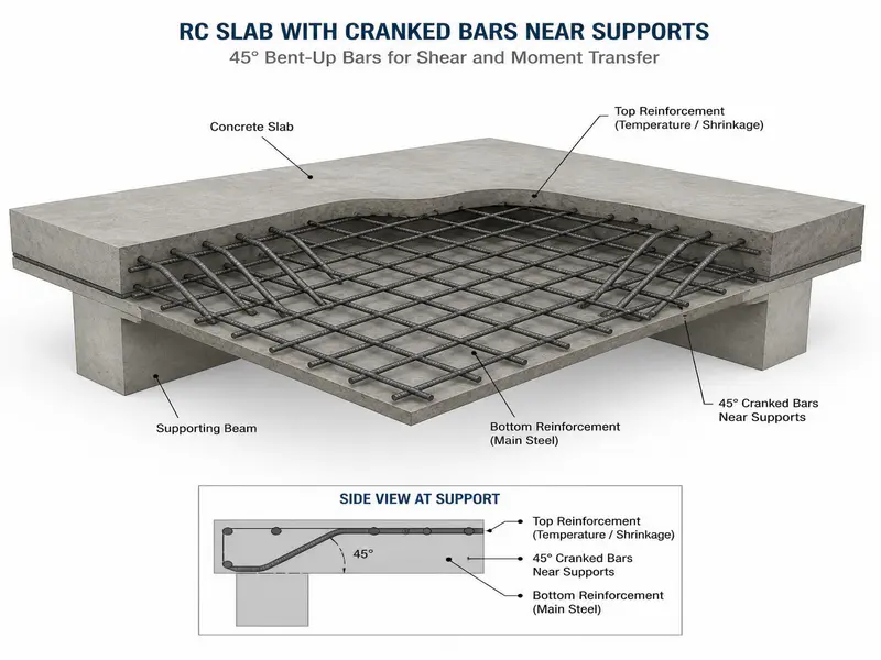
In real-world construction, slabs are rarely flat grids. They feature “cranked bars” (bent-up bars) near the supports to resist negative bending moments (hogging) over the beams.
Let’s look at a two-way slab where bars are cranked at an angle of 45 degrees on both ends.
Additional Engineering Rules for Cranked Bars:
- When a bar is bent up at 45 degrees, its overall length increases. The extra length added for each crank is 0.42 x h, where h is the vertical distance between the top and bottom steel grids.
- h = Total Slab Thickness – (2 x Clear Cover) – (Diameter of Bar)
Given Site Data:
- Slab Dimensions = 5 metres x 4 metres
- Slab Thickness = 150 mm (0.15 metres)
- Clear Cover = 20 mm
- Main Bars (along 4-metre span) = 10 mm diameter at 150 mm spacing, cranked at both ends.
- Distribution Bars (along 5-metre span) = 8 mm diameter at 150 mm spacing, cranked at both ends.
Step 1: Calculate the Crank Height (h)
- h = 150 mm – (2 x 20 mm) – 10 mm = 150 – 40 – 10 = 100 mm = 0.1 metres
Step 2: Calculate Main Bars (10 mm) Running Along the 4-Metre Span
- Clear distance for calculating number of bars = 5 metres – (2 x 0.020) = 4.96 metres
- Number of 10 mm bars = (4.96 / 0.15) + 1 = 33.06 + 1 = 34.06 –> 35 bars
- Length of one straight bar before cranking = 4 metres – (2 x 0.020) = 3.96 metres
- Add extra length for two cranks at both ends = 2 x (0.42 x h) = 2 x (0.42 x 0.1) = 0.084 metres
- Total length of one cranked main bar = 3.96 + 0.084 = 4.044 metres
- Total length of all main bars = 35 bars x 4.044 metres = 141.54 metres
- Unit weight of 10 mm bar = (10 x 10) / 162 = 0.617 kg/m
- Total Weight of 10 mm Bars = 141.54 x 0.617 = 87.33 kg
Step 3: Calculate Distribution Bars (8 mm) Running Along the 5-Metre Span
- Clear distance for calculating number of bars = 4 metres – (2 x 0.020) = 3.96 metres
- Number of 8 mm bars = (3.96 / 0.15) + 1 = 26.4 + 1 = 27.4 –> 28 bars
- Length of one straight bar before cranking = 5 metres – (2 x 0.020) = 4.96 metres
- Add extra length for two cranks = 2 x (0.42 x 0.1) = 0.084 metres
- Total length of one cranked distribution bar = 4.96 + 0.084 = 5.044 metres
- Total length of all distribution bars = 28 bars x 5.044 metres = 141.23 metres
- Unit weight of 8 mm bar = (8 x 8) / 162 = 0.395 kg/m
- Total Weight of 8 mm Bars = 141.23 x 0.395 = 55.79 kg
Step 4: Final Tally
- Total Steel Weight = 87.33 kg + 55.79 kg = 143.12 kg
Thumb Rules for Civil Engineers (Quick Verification)
When you are standing on-site supervising a concrete pour, you will not always have a calculator or the drawings handy to perform full Bar Bending Schedules (BBS). Civil engineers use standard structural thumb rules to cross-check structural drawings quickly.
The Percentage Volume Rule
On average, structural steel reinforcement occupies a specific percentage of the total concrete volume depending on the structural element.
- For Slabs: 0.7% to 1.0% of the total volume of concrete consists of steel.
- For Beams: 1.0% to 2.0% of the concrete volume.
- For Columns: 1.0% to 5.0% of the concrete volume.
Quick Calculation Using the Thumb Rule:
If you have a slab with a concrete volume of 10 cubic metres, you can estimate the steel weight using these steps:
- Take 1% of the concrete volume: 10 x 0.01 = 0.1 cubic metres of steel.
- Multiply by the density of steel (7850 kg/m3): 0.1 x 7850 = 785 kg.
If your manual step-by-step calculation yields 1500 kg or 300 kg for that same slab, you immediately know you have made a major math error.
Material and Volumetric Conversions for Site Managers
Material orders across different processing plants, vendors, and countries use varying measurement scales. To ensure clear communication on-site, use these standard conversion factors.
- 1 Metric Ton (MT) = 1,000 Kilograms (kg)
- 1 Quintal = 100 Kilograms (kg)
- 1 Cubic Metre (cum) = 35.314 Cubic Feet (CFT)
- 1 Brass (Common Indian Site Unit for Aggregates/Concrete) = 100 Cubic Feet (CFT) = 2.831 Cubic Metres
Site Quality Control, Overlaps, and Wastage Management

Calculating structural steel needs on paper is straightforward, but physical installation introduces real-world variables. A competent civil engineer must factor in the following field realities:
1. Lapping Length (Overlapping Bars)
Because standard rebar pieces are manufactured to a maximum length of 12 metres, you will have to join two bars together if your slab span is wider than 12 metres. This joining area is called an overlap or lap length.
- Tension Lap Length Rule: For slabs, the lap length is generally calculated as 50D (50 times the diameter of the bar).
- Example: If you are overlapping a 10 mm bar, the lap length must be 50 x 10 mm = 500 mm (0.5 metres). This length must be added to your total length calculations.
2. Structural Chairs
When constructing a two-way slab with cranked bars or a double-mesh heavy foundation slab, the top steel grid tends to sag under the weight of workers pouring concrete.
- Chairs are Z-shaped or inverted U-shaped, small steel support bars placed between the top and bottom meshes to maintain the design gap.
- Always add roughly 1% to 2% to your total structural steel calculations to account for the weight of these support chairs.
3. Wastage Factors
Rebar cutting optimisations are rarely perfect. Small scraps, bent ends, and rust scaling lead to material loss.
- For small residential projects, add a 5% wastage allowance to the calculated total weight.
- For large commercial projects managed via automated cutting software, reduce this allowance to 3%.
On-Site Quality Check Checklist Before Concreting
Before authorising a concrete mix pour over your newly laid steel slab grid, conduct this physical on-site audit:
- Diameter Verification: Use a vernier calliper to check that the correct bar diameter (e.g., 12 mm instead of 10 mm) has been installed as per the structural drawings.
- Spacing Consistency: Measure the gap between bars at five random spots across the slab. Ensure it does not deviate by more than 10 mm from the design specification.
- Cover Block Placement: Verify that concrete cover blocks (20 mm to 25 mm thick) are placed under the bottom steel mesh at intervals of 1 metre. This prevents the steel from being exposed to air and rusting after the formwork is stripped.
- Binding Wire Quality: Ensure all intersections of main and distribution bars are tightly secured using 18-gauge annealed binding wire. Loose bars shift position under the heavy impact of pouring concrete.
Frequently Asked Questions (FAQs)
1. What is the standard density of steel used in construction calculations?
The standard density of structural mild steel and thermo-mechanically treated (TMT) bars used in civil engineering calculations is 7850 kilograms per cubic metre (kg/m3).
2. Can I use the (D x D) / 162 formula for high-strength TMT bars like Fe500 or Fe550?
Yes. The grade of steel (Fe415, Fe500, Fe550) represents its yield strength, not its density. The physical weight and density of structural steel remain identical across all performance grades, meaning the standard unit weight formula applies to all of them.
3. What happens if I forget to subtract the clear cover during slab steel calculations?
If you forget to subtract the concrete cover, your calculated rebar lengths will be longer than the physical size of the formwork box. The steel bars will extend past the edge of the slab, meaning workers will have to manually cut every bar down on-site, creating massive unnecessary material waste.
4. Why is the spacing of distribution bars usually larger than that of main bars?
Main reinforcement bars are designed to carry the primary bending loads, which are concentrated across the shorter span. Distribution bars are only responsible for resisting secondary temperature changes, shrinkage cracks, and distributing minor localized loads, meaning they require less steel and wider spacing.
5. How much binding wire is required per ton of steel slab reinforcement?
As a standard engineering rule of thumb, approximately 7 to 10 kilograms of binding wire are consumed to tie 1 Metric Ton (1,000 kg) of slab steel reinforcement.
As per IS 456:2000 (Plain and Reinforced Concrete Code), slab reinforcement design must follow structural safety guidelines.
Conclusion
Calculating the steel weight for a concrete slab is a fundamental skill that bridges theoretical structural engineering with practical on-site construction management. By mastering the core unit weight formulas, understanding the geometric adjustments needed for cranked bars and overlaps, and applying consistent quality control measures on-site, you can eliminate material shortages and prevent budget overruns.
Always cross-check your detailed bar-bending schedules against structural thumb rules before placing your final material procurement order with steel vendors.
Shakeel T is a qualified Civil Engineer and Structural Consultant with extensive on-site experience in residential and commercial building construction. Specializing in material estimation, cost budgeting, and structural safety guidelines, he has successfully managed multiple real estate projects from foundation to finishing. Through this blog, Shakeel shares field-tested civil engineering thumb rules, IS Code practices, and practical site tips to help home builders execute their projects efficiently and within budget.
Education: Diploma in Civil Engineering
Expertise: Quantity Surveying, Material Estimation, Structural Design, and Site Management.