Introduction
An improperly sized column is a structural disaster waiting to happen. In residential construction, columns act as the vertical pillars that transmit the entire load of the structure—including slabs, beams, walls, and live loads—down to the foundations and the soil below.
Choosing the correct column size for 1 2 and 3 storey building projects is not something you can guess. Oversizing columns wastes money on excess concrete and steel reinforcement, driving up material costs needlessly. Undersizing them, however, can lead to structural cracking, severe deformation, or catastrophic building collapse.
This comprehensive engineering guide breaks down standard thumb rules, structural requirements, step-by-step load calculations, and critical on-site quality control checklists for multi-storey residential buildings.

Quick Reference: Standard Column Sizes & Reinforcement Settings
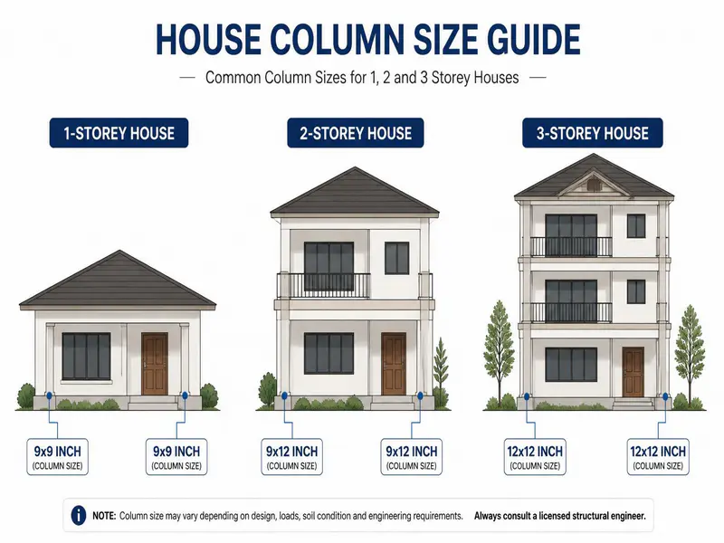
For a quick reference during initial planning or peer review, the table below outlines the standard minimum column sizes, concrete grades, and steel reinforcement requirements for 1, 2, and 3-storey residential buildings. These values assume a standard span (distance between two columns) of no more than 4.5 metres (approx. 15 feet).
| Building Height | Minimum Column Size (Inches) | Minimum Column Size (Millimetres) | Minimum Concrete Grade | Main Longitudinal Bars (Minimum) | Lateral Ties (Stirrups) Size & Spacing |
|---|---|---|---|---|---|
| 1 Storey (G+0) | 9″ x 9″ or 9″ x 12″ | 230mm x 230mm or 230mm x 300mm | M20 (1:1.5:3) | 4 bars of 12mm diameter | 8mm diameter @ 150mm c/c |
| 2 Storey (G+1) | 9″ x 12″ or 12″ x 12″ | 230mm x 300mm or 300mm x 300mm | M20 / M25 | 6 bars of 12mm diameter | 8mm diameter @ 150mm c/c |
| 3 Storey (G+2) | 12″ x 12″ or 12″ x 15″ | 300mm x 300mm or 300mm x 380mm | M25 (1:1:2) | 6 bars of 16mm diameter | 8mm diameter @ 100mm to 150mm c/c |
Note: Always consult a licensed structural engineer to verify site-specific wind, seismic, and actual soil-bearing capacity conditions before starting construction.
Read also: Cement Required for 1000 Sq Ft House
Fundamental Structural Rules for Column Design
Before looking at specific building heights, every builder, contractor, and engineer must understand the core structural rules governing column design. These rules are derived from international building standards and standard engineering practices.
1. The Distance Between Columns (Span Length)
The sizes listed in this guide assume a maximum column-to-column distance of 4.5 metres to 5 metres. If your architectural layout requires large open spaces with spans exceeding 5 metres, the column cross-sectional area and steel percentages must increase significantly to handle the additional bending moments.
2. Minimum Concrete Grade
Never use a concrete mix lower than M20 (1 part Cement : 1.5 parts Sand : 3 parts Coarse Aggregate) for structural columns. For 3-storey buildings, M25 concrete is highly recommended to provide better compressive strength and resistance against environmental degradation.
3. Steel Reinforcement Percentage
According to standard building codes, the longitudinal reinforcement in a column must be:
- Minimum Steel: 0.8% of the total cross-sectional area of the column.
- Maximum Steel: 6.0% of the total cross-sectional area (practically limited to 4.0% to avoid congestion during concrete pouring).
4. Minimum Bar Diameter
Never use steel bars thinner than 12mm for the main vertical (longitudinal) reinforcement of a load-bearing column.
Comprehensive Breakdown by Building Height
1. Column Size for a 1-Storey Building (G+0 / Ground Floor Only)
A single-storey residential building carries relatively light loads, primarily consisting of its own roof slab, beams, walls, and a minimal rooftop live load.
- Recommended Size: 9 inches x 9 inches (230mm x 230mm) or 9 inches x 12 inches (230mm x 300mm).
- Steel Specification: 4 vertical bars of 12mm diameter (Fe500 or Fe550 TMT bars).
- Lateral Ties: 8mm diameter bars spaced at 150mm center-to-center.
- Practical Site Tip: While a 9″x9″ column works well under standard conditions, using a 9″x12″ layout gives you better structural flexibility if you decide to add an extra floor in the future.
2. Column Size for a 2-Storey Building (G+1 Floor)
A two-storey building experiences double the dead load and must withstand greater buckling forces on the ground floor columns.
- Recommended Size: 9 inches x 12 inches (230mm x 300mm) or 12 inches x 12 inches (300mm x 300mm).
- Steel Specification: 6 vertical bars of 12mm diameter. Alternatively, use 4 bars of 16mm diameter at the corners.
- Lateral Ties: 8mm diameter bars spaced at 150mm center-to-center. At beam-column joints, reduce this spacing to 100mm to handle high shear stress.
- Concrete Quality: Strictly maintain an M20 grade or higher with a water-cement ratio of 0.45 to 0.50.
3. Column Size for a 3-Storey Building (G+2 Floors)
Three-storey buildings carry substantial cumulative weight. The ground floor columns are subject to high compressive loads combined with multi-directional bending moments caused by wind and minor tremors.
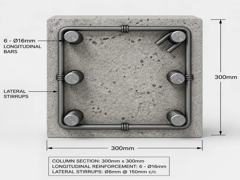
- Recommended Size: 12 inches x 12 inches (300mm x 300mm) or 12 inches x 15 inches (300mm x 380mm).
- Steel Specification: 6 vertical bars of 16mm diameter. For columns handling larger spans, use 4 bars of 20mm at the corners and 2 bars of 16mm in the middle.
- Lateral Ties: 8mm diameter bars. Spacing should be kept tight at 100mm center-to-center near the joints, and 150mm in the middle third of the column height.
- Concrete Quality: Use M25 grade concrete. Ensure proper mechanical vibration during pouring to eliminate air voids.
Structural Load Calculation Methodology
To understand how these sizes are determined, engineers calculate the total load acting on a column using tributary area analysis. Below is the exact step-by-step mathematical method used to safely evaluate column requirements.
Core Mathematical Formulas (Plain Text)
- Total Column Load (P) = Ultimate Dead Load + Ultimate Live Load
- Concrete Compressive Strength Contribution = 0.4 x fck x Ac
- Steel Tensile Strength Contribution = 0.67 x fy x Asc
- Total Column Capacity = Concrete Contribution + Steel Contribution
- Wet Volume of Concrete = Dry Volume x 1.54
Where:
- fck = Characteristic compressive strength of concrete (e.g., 20 N/mm2 for M20).
- fy = Yield strength of steel (e.g., 500 N/mm2 for Fe500).
- Ac = Net cross-sectional area of concrete.
- Asc = Total cross-sectional area of steel bars.
Step-by-Step Practical Example
Let’s calculate the total load on a ground-floor column for a standard 3-Storey (G+2) Residential Building with a tributary area of 4 metres x 4 metres (16 square metres).
Step 1: Calculate Dead Load per Floor
- Slab Load: A standard 125mm thick slab weighs 3.125 kN/m2. Including floor finishes, assume 4.0 kN/m2.
- Beam Load: A standard 230mm x 450mm beam weighs approx. 2.5 kN per linear metre.
- Wall Load: A 230mm thick brick wall at a height of 3 metres weighs approx. 12 kN per linear metre.
For a 16m2 tributary area, the typical dead load per floor (combining slab, self-weight of beams, and walls) averages roughly 10 kN/m2.
- Dead Load per Floor = 16 m2 x 10 kN/m2 = 160 kN.
Step 2: Calculate Live Load per Floor
Residential live load standard is 2.0 kN/m2.
- Live Load per Floor = 16 m2 x 2.0 kN/m2 = 32 kN.
Step 3: Total Load for 3 Floors (G+2)
- Total Load per Floor = 160 kN (Dead) + 32 kN (Live) = 192 kN.
- Total Load for 3 Floors = 192 kN x 3 floors = 576 kN.
Step 4: Apply Safety Factor
Engineers apply a standard limit state load factor of 1.5.
- Ultimate Design Load (Pu) = 576 kN x 1.5 = 864 kN.
Step 5: Verify Column Capacity
Let’s verify if a 300mm x 300mm (12″ x 12″) column with M25 concrete and 6 bars of 16mm steel can safely carry this 864 kN load.
- Total Area (Ag) = 300mm x 300mm = 90,000 mm2.
- Area of Steel (Asc) for 6 bars of 16mm = 6 x 201 mm2 = 1,206 mm2.
- Area of Concrete (Ac) = 90,000 – 1,206 = 88,794 mm2.
Using the column capacity formula:
- Concrete Capacity = 0.4 x 25 N/mm2 x 88,794 mm2 = 887,940 N = 887.94 kN
- Steel Capacity = 0.67 x 500 N/mm2 x 1,206 mm2 = 404,010 N = 404.01 kN
- Total Safe Capacity = 887.94 + 404.01 = 1,291.95 kN.
Since the Safe Capacity (1,291.95 kN) is significantly higher than the Design Load (864 kN), the 12″ x 12″ column size is structurally safe and perfectly optimized for this G+2 configuration.

Column design in India is generally done according to the guidelines mentioned in the IS 456:2000 code for reinforced concrete structures.
Material Estimations & Unit Conversions
On real construction sites, materials are ordered using various regional metrics. Knowing how to convert these units helps prevent ordering errors and keeps your budget on track.
Crucial Conversion Rules
- 1 Cubic Metre (cum) = 35.314 Cubic Feet (CFT)
- 1 Metric Ton = 1,000 Kilograms (kg)
- 1 Brass (used for aggregate/sand) = 100 Cubic Feet (CFT) = 2.83 Cubic Metres
Example: Estimating Materials for a 12″ x 12″ x 10′ Column
To cast one column of size 0.3m x 0.3m with a height of 3 metres (approx 10 feet) using M25 concrete:
- Wet Volume Required: 0.3 x 0.3 x 3.0 = 0.27 cubic metres.
- Dry Volume Needed: 0.27 x 1.54 (shrinkage/wastage factor) = 0.4158 cubic metres.
- Using an M25 mix ratio (1:1:2), the material breakdown for this single column is:
- Cement: 5.7 Bags (approx. 285 kg)
- Sand: 14.7 CFT (0.415 cubic metres)
- Coarse Aggregate (20mm): 29.4 CFT (0.83 cubic metres)
On-Site Quality Control & Common Pitfalls
Even a perfectly designed column will fail if it is poorly built on-site. Follow this professional engineering checklist during execution:
1. Concrete Cover Preservation
Always use heavy-duty plastic or concrete spacer blocks to ensure a strict clear cover of 40mm around the steel cage. Without this cover, moisture will penetrate the concrete, causing the steel reinforcement to rust, expand, and spall away the concrete skin.
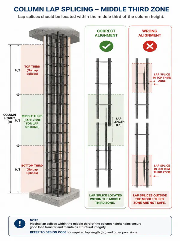
2. Lap Splicing Rules
Never lap bars at the exact beam-column junction or at the bottom floor level where bending moments are at their highest. All steel bars must be lapped at the middle third zone of the column height. Always stagger the laps so that no more than 50% of the bars are spliced at the same cross-section.
3. Shuttering Alignment & Verticality Checklist
Before pouring concrete, use a traditional heavy plumb-bob or a digital laser level to verify that the formwork shuttering is perfectly vertical. A column that is misaligned by even 1 or 2 centimetres develops an unintended eccentricity, inducing secondary bending stresses that the column was never designed to handle.
4. Compaction and Curing Guidelines
- Compaction: Pour concrete in controlled layers of 300mm to 450mm and compact it using a 40mm mechanical needle vibrator. Do not hold the vibrator against the steel cage, as this creates localized gaps between the steel and the concrete mix.
- Curing: Strip the formwork after 24 to 48 hours and immediately wrap the raw concrete columns in wet hessian (burlap) sheets. Keep these sheets continuously damp for at least 7 to 10 days to achieve the full target compressive strength.
Frequently Asked Questions (FAQs)
1.What is the absolute minimum column size for a residential building?
According to general building codes, the absolute minimum size for a load-bearing column is 9 inches x 9 inches (230mm x 230mm) using M20 grade concrete and 4 bars of 12mm TMT steel. This size should only be used for single-storey (G+0) structures with small spans.
2.Can I use 10mm steel bars as the main reinforcement in a column?
No. Standard engineering practice and structural building codes explicitly prohibit using bars smaller than 12mm for longitudinal load-bearing column reinforcement. 10mm bars do not offer sufficient resistance against structural buckling forces.
3.What happens if the columns in a 3-storey building are misaligned?
Misaligned columns cause eccentricity, meaning the vertical load from above is no longer tracking straight down the center of the column. This creates unexpected bending forces that can lead to structural cracking, wall separation, or sudden structural failure.
4.Can I increase the distance between columns to 7 metres using a 9″x12″ column?
No. A 9″ x 12″ column is not safe for a 7-metre span. As the span increases, the load and bending moments grow exponentially. For a 7-metre span, you will need a significantly larger column profile, likely 12″ x 18″ or larger, paired with high-performance M25 or M30 concrete and an engineered steel configuration.
5.How long should column formwork remain in place before removal?
For vertical structural members like columns, formwork shuttering can safely be removed after 24 to 48 hours, provided the concrete has set sufficiently to support its own weight. Once removed, moist curing must begin immediately.
Structural engineers calculate column loads and reinforcement details using standard structural design principles followed worldwide.
Summary and Conclusion
Determining the right column size for 1 2 and 3 storey building projects requires carefully balancing architectural needs with structural safety.
- For 1-storey homes, a 9″x9″ column is generally sufficient.
- For 2-storey homes, step up to a minimum of 9″x12″.
- For 3-storey structures, use a robust 12″x12″ or 12″x15″ configuration.
Never cut corners on material grades, steel diameters, or curing practices. While thumb rules provide an excellent starting point for initial budgeting and spatial planning, always hire a certified structural engineer to run a complete analysis of your specific floor plans, soil conditions, and regional wind/seismic factors before pouring concrete.
Shakeel T is a qualified Civil Engineer and Structural Consultant with extensive on-site experience in residential and commercial building construction. Specializing in material estimation, cost budgeting, and structural safety guidelines, he has successfully managed multiple real estate projects from foundation to finishing. Through this blog, Shakeel shares field-tested civil engineering thumb rules, IS Code practices, and practical site tips to help home builders execute their projects efficiently and within budget.
Education: Diploma in Civil Engineering
Expertise: Quantity Surveying, Material Estimation, Structural Design, and Site Management.