Introduction
Every structural engineer and seasoned site builder knows that a building is only as strong as its foundation. While foundations transfer heavy structural loads safely to the soil below, a critical intermediate component acts as the ultimate horizontal tie for your building: the plinth beam.
In residential and commercial building construction, omitting or poorly constructing this single element can lead to catastrophic structural failures, uneven settlement cracks, and persistent dampness issues.
This comprehensive engineering guide breaks down everything you need to know about the plinth beam in construction, including its core purpose, standard sizing, reinforcement design, structural calculations, and on-site execution checklists.
What is a Plinth Beam?
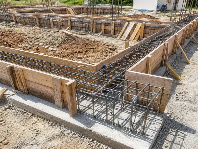
A plinth beam in construction is a reinforced concrete (RCC) beam constructed at the plinth level the point where the substructure (foundation) ends and the superstructure (walls and columns) begins. It runs horizontally across the entire perimeter of the building and connects all the isolated columns together.
Typically constructed just above the natural ground level, the plinth beam creates a robust structural transition zone. It ensures that the building acts as a single cohesive unit when subjected to shifting soils or seismic activity.
Core Purposes and Technical Functions
A plinth beam is not just an optional framework; it serves several irreplaceable engineering functions:
- Prevention of Differential Settlement: If one column settles into the soil slightly more than an adjacent column, it induces massive shear stress in the masonry walls. The plinth beam ties the columns together, distributing loads evenly and eliminating differential settlement.
- Load Distribution: It carries the dead load of the brick or concrete block masonry walls built above it and safely transfers that weight directly to the columns and foundations.
- Retention of Backfill Soil: The area inside the foundation is backfilled with soil and sand to raise the floor level. The plinth beam acts as a retaining wall, preventing this internal compacted soil from pushing outward and causing floor cave-ins.
- Moisture Barrier (Anti-Dampness): Acting as a physical barrier, it stops capillary water from rising from the wet ground soil up into the superstructure masonry walls, preventing peeling paint and damp patches.
- Seismic and Lateral Tie: During earthquakes, windstorms, or lateral earth movements, the plinth beam serves as a horizontal tie-beam that prevents columns from splaying or buckling outward.
Concrete quantity estimation is essential during beam construction. Use our concrete calculator formula guide to easily calculate the required concrete for construction works.
Standard Sizing and Dimensions
The dimensions of a plinth beam depend heavily on the total number of storeys (floors), the span between columns, and the thickness of the masonry walls planned above it.
Minimum Width
The width of the plinth beam should match or exceed the thickness of the superstructure wall.
- For standard 9-inch brick walls, the minimum plinth beam width is 230 mm (9 inches).
- For lightweight or internal 4.5-inch walls, a minimum width of 200 mm is still recommended for structural integrity.
Minimum Depth
The depth of the beam handles the bending moments caused by the wall load.
- For standard residential buildings (G+1 or G+2) with column spans under 4 metres, the minimum depth is 230 mm to 300 mm (9 to 12 inches).
- For longer spans (above 4.5 metres) or higher structural loads, the depth is increased to 375 mm, 450 mm, or 600 mm.
Understanding the correct footing size is important before constructing the plinth beam. Read our detailed guide on footing size calculation for residential buildings to learn how foundation dimensions are determined.
Reinforcement Specification Guide
Reinforced Cement Concrete requires a precise balance of steel and concrete. Below are the standard minimum specifications based on Indian Standards (IS 456:2000) and general international building codes for low-to-medium rise residential construction.

Longitudinal (Main) Reinforcement
- Top Bars: Minimum of 2 bars of 10 mm or 12 mm diameter high-yield strength deformed (Fe500/Fe550) bars.
- Bottom Bars: Minimum of 2 bars of 12 mm diameter. If the span is long or holds a double-storey brick wall, 3 bars of 12 mm or 2 bars of 16 mm are used.
Transverse Reinforcement (Stirrups / Shear Ties)
- Diameter: Minimum 8 mm diameter mild steel or TMT bars.
- Spacing: Spaced at 150 mm (6 inches) center-to-center in the middle zone of the beam. Near the column joints (critical shear zones), the spacing must be compressed to 100 mm (4 inches) center-to-center.
Clear Concrete Cover
- To protect the steel bars from moisture, corrosion, and environmental attacks, a minimum clear concrete cover of 25 mm to 30 mm must be strictly maintained using concrete cover blocks.
Core Mathematical Formulas for Material Estimation
To calculate the exact volume of concrete and weight of steel required for a plinth beam, site engineers use specific plain-text engineering formulas.
Concrete Volume Calculation
- Total Wet Volume of Concrete = Total Length of Plinth Beam x Width of Beam x Depth of Beam
- Dry Volume of Concrete = Total Wet Volume of Concrete x 1.54 [1]
Note: The factor 1.54 accounts for the volume shrinkage that occurs when dry sand, cement, and aggregate are mixed with water.
Mix Proportioning (For M20 Grade Concrete – 1:1.5:3 Ratio)
- Sum of Ratio Parts = 1 + 1.5 + 3 = 5.5
- Volume of Cement = (1 / 5.5) x Dry Volume of Concrete
- Number of Cement Bags = Volume of Cement / 0.0347 (Since 1 bag of cement equals 0.0347 cubic metres)
- Volume of Sand = (1.5 / 5.5) x Dry Volume of Concrete
- Volume of Coarse Aggregate = (3 / 5.5) x Dry Volume of Concrete
Steel Weight Calculation
- Weight of Steel Bar per Metre = (Diameter x Diameter) / 162
- Total Weight = Weight per Metre x Total Length of Bar (including development lengths and overlaps)
Practical Step-by-Step Estimation Examples
Let us look at a real-world site scenario to apply these equations.
Example 1: Concrete Material Estimation
Suppose you are constructing a residential house where the total running perimeter length of all interconnected plinth beams is 50 metres. The chosen cross-section size of the plinth beam is 230 mm width by 300 mm depth.
Step 1: Convert all units to Metres
- Length = 50 m
- Width = 0.23 m
- Depth = 0.30 m
Step 2: Calculate Wet Volume
- Wet Volume = 50 x 0.23 x 0.30
- Wet Volume = 3.45 Cubic Metres (m3)
Step 3: Calculate Dry Volume
- Dry Volume = 3.45 x 1.54 = 5.313 Cubic Metres (m3)
Step 4: Calculate Component Quantities for M20 Grade (1:1.5:3)
- Cement Volume = (1 / 5.5) x 5.313 = 0.966 m3
- Total Cement Bags = 0.966 / 0.0347 = 27.83 bags (Round up to 28 Bags)
- Sand Volume = (1.5 / 5.5) x 5.313 = 1.449 m3
- Aggregate Volume = (3 / 5.5) x 5.313 = 2.898 m3
Example 2: Reinforcement (Steel) Weight Estimation
Using the same 50-metre long plinth beam layout, let us calculate the steel reinforcement weight. Assume the design requires 4 main longitudinal bars of 12 mm diameter and 8 mm stirrups spaced at 150 mm center-to-center.
Part A: Main Longitudinal Bars
- Total Length of 1 Bar = 50 metres (ignoring overlaps for simplicity)
- Number of Bars = 4
- Total Length for 4 Bars = 50 x 4 = 200 metres
- Weight of 12 mm Bar per Metre = (12 x 12) / 162 = 144 / 162 = 0.888 kg/m
- Total Weight of Main Bars = 200 x 0.888 = 177.6 kg
Part B: Stirrups (Shear Ties)
- Beam Cross-Section = 230 mm x 300 mm
- Deducting 25 mm clear cover from all four sides gives a stirrup size of:
- Stirrup Width (a) = 230 – (25 x 2) = 180 mm = 0.18 m
- Stirrup Height (b) = 300 – (25 x 2) = 250 mm = 0.25 m
- Cutting Length of 1 Stirrup = (2 x a) + (2 x b) + Hook Lengths
- Cutting Length = (2 x 180) + (2 x 250) + 120 mm = 360 + 500 + 120 = 980 mm = 0.98 m
- Total Number of Stirrups Required = (Total Beam Length / Spacing) + 1
- Number of Stirrups = (50 / 0.15) + 1 = 333.33 + 1 = 335 Stirrups
- Total Length of 8 mm Steel required = 335 stirrups x 0.98 m = 328.3 metres
- Weight of 8 mm Bar per Metre = (8 x 8) / 162 = 64 / 162 = 0.395 kg/m
- Total Weight of Stirrups = 328.3 x 0.395 = 129.68 kg
Part C: Total Steel Weight
- Total Steel Needed = 177.6 kg + 129.68 kg = 307.28 kg
Materials Unit Conversions & Quick Reference Table
Construction materials are bought, quantified, and measured in different regional or international units depending on commercial supply chains. Use the clean conversion guide below to change units smoothly.
Key Material Conversion Equivalents
- 1 Cubic Metre (m3) = 35.314 Cubic Feet (CFT)
- 1 Brass (Standard Indian local unit) = 100 Cubic Feet (CFT) = 2.831 Cubic Metres (m3)
- 1 Metric Ton = 1000 Kilograms (kg) = 10 Quintals
Comprehensive Material Estimation Reference Table
This table simplifies material ordering for different standard lengths of a 230 mm x 300 mm Plinth Beam using an M20 Concrete Mix (1:1.5:3) and standard reinforcement parameters.
| Total Beam Length (Metres) | Total Wet Concrete Volume (m3) | Total Concrete Volume (CFT) | Cement Bags Needed (M20 Grade) | Sand Needed (CFT) | Coarse Aggregates (CFT) | Total Steel Weight (kg) |
|---|---|---|---|---|---|---|
| 10 Metres | 0.69 m3 | 24.36 CFT | 6 Bags | 10.15 CFT | 20.30 CFT | 61.50 kg |
| 25 Metres | 1.73 m3 | 61.09 CFT | 14 Bags | 25.56 CFT | 51.12 CFT | 153.64 kg |
| 50 Metres | 3.45 m3 | 121.83 CFT | 28 Bags | 51.17 CFT | 102.34 CFT | 307.28 kg |
| 100 Metres | 6.90 m3 | 243.67 CFT | 56 Bags | 102.34 CFT | 204.68 CFT | 614.56 kg |
On-Site Construction Process & Quality Control Checklist
Executing a plinth beam layout perfectly requires structured attention to detail during formwork erection, steel tying, and casting.
Step-by-Step Construction Sequence
- Excavation and Levelling: Excavate the ground surface along the brick walls to reach the exact foundation tie level. Compact the soil layer beneath the beam location completely.
- PCC Bedding Construction: Lay a thin 50 mm to 75 mm layer of Plain Cement Concrete (PCC) of M10 grade (1:3:6 ratio) across the trench. This creates a level, hard, dirt-free base plane for the structural plinth beam.
- Reinforcement Cage Laying: Fix the main reinforcement steel cage directly over the cover blocks on top of the cured PCC bed. Ensure the structural development lengths (L-bends) anchor firmly inside the column junctions.
- Formwork Shutting: Install sturdy wooden shuttering planks or steel structural plate formworks. Secure them tightly with external props, braces, and tie-wires so they do not bulge laterally under the weight of wet concrete.
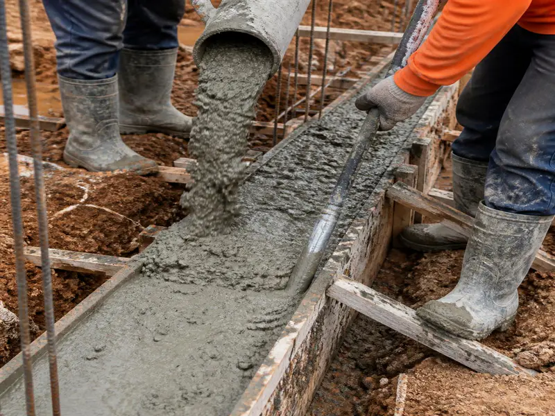
- Pouring and Compaction: Pour freshly mixed concrete cleanly inside the formwork channels. Use a mechanical needle vibrator continuously to remove trapped air voids and eliminate honeycombing structures inside the core matrix.
- Curing Phase: Remove the formwork carefully after 24 hours. Keep the exposed structural concrete surface constantly wet using moist hessian bags or ponding water for a minimum duration of 7 to 10 days.
Quality Control and Engineering Precautions
- Wastage Factor Calculations: Always order 5% to 7% extra concrete ingredients to account for unavoidable spillages, mixing losses, and slight trench irregularities on-site. For reinforcement steel, factor in a 10% structural wastage allowance for cut-pieces, lapping profiles, and bending margins.
- Lap Length Rules: Never locate a bar overlap joint at the center of the beam span where tension stresses peak. Always stagger joints across different sections. Use a standard minimum lap length parameter of 50D (where D represents the diameter of the bar).
- The Anti-Dampness Additive Check: To make the plinth beam an absolute waterproofing barrier, mix high-quality liquid integral waterproofing compounds into the concrete batch according to manufacturer guidelines.
Frequently Asked Questions (FAQs)
Q1. Is a plinth beam absolutely mandatory for single-storey (Ground Floor) buildings?
Yes. Even for low-load Ground Floor structures, a plinth beam is necessary. It shields the upper brick walls from moisture absorption from the ground and prevents cracks if the topsoil shifts or erodes.
Q2. What is the fundamental difference between a Plinth Beam and a Tie Beam?
While both are horizontal structures tying columns together, their location and load profile differ. A plinth beam is cast specifically at ground or floor level and carries direct load from brick walls. A tie beam is cast at any level above the plinth (e.g., roof or intermediate level) primarily to reduce the effective length of long columns and resist lateral loads, carrying minimal wall weight.
Q3. Can we build the plinth beam directly on raw, uncompacted soil?
No. Constructing a plinth beam over loose soil causes it to sag or settle under its own weight during casting. Always lay a firm, levelled 50mm to 75mm thick Plain Cement Concrete (PCC) base layer before placing reinforcement cages.
Q4. What happens if the concrete cover blocks are omitted during construction?
Omitting cover blocks causes the internal steel bars to sit directly against the formwork or base soil. Once the formwork is removed, the steel is exposed to the atmosphere. This accelerates rust and corrosion, leading to spalling concrete and premature structural failure.
Q5. When is the best time to apply a Damp Proof Course (DPC) relative to the plinth beam?
The Damp Proof Course layer is applied directly on the cured, clean top surface of the completed plinth beam before laying the first course of masonry bricks.
You can also learn more about structural engineering formulas and construction materials from Engineering Toolbox, which provides reliable engineering resources and technical explanations.
Conclusion
The plinth beam is a foundational component of structural safety in modern building design. By serving as an unbreakable horizontal tie framework, it evenly distributes masonry wall loads, absorbs seismic movements, and prevents ground dampness from damaging internal finishes.
As a site engineer, contractor, or homebuilder, keeping structural sizes correct, utilizing clean material ratios (like M20 concrete), and maintaining rigorous on-site quality checklists ensures your project remains durable and free from structural cracks for generations.
To ensure your layout meets structural guidelines, confirm that your local construction site plans match these dimension scales and reinforcement configurations.
Shakeel T is a qualified Civil Engineer and Structural Consultant with extensive on-site experience in residential and commercial building construction. Specializing in material estimation, cost budgeting, and structural safety guidelines, he has successfully managed multiple real estate projects from foundation to finishing. Through this blog, Shakeel shares field-tested civil engineering thumb rules, IS Code practices, and practical site tips to help home builders execute their projects efficiently and within budget.
Education: Diploma in Civil Engineering
Expertise: Quantity Surveying, Material Estimation, Structural Design, and Site Management.
Nice information