Introduction
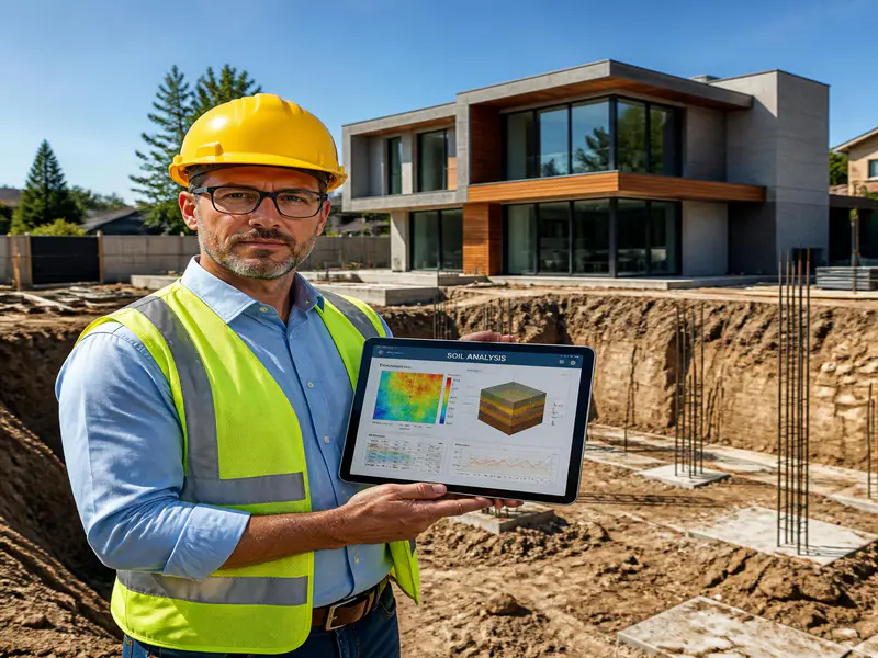
Building a home is likely the most significant financial investment you will ever make. While home buyers spend weeks choosing architectural styles, paint colors, and interior fixtures, the most critical part of the house is completely invisible once completed: the ground beneath it. [1]
Every structure relies entirely on the strength of the soil it sits on. If the soil fails, the building fails. In civil engineering, this fundamental property is known as Soil Bearing Capacity.
Whether you are a structural engineer designing a foundation, a builder executing a project on-site, or a homeowner planning your dream house, understanding soil bearing capacity is non-negotiable. This comprehensive guide breaks down the core science, mathematical formulas, on-site testing methods, and practical calculations to ensure your structure stands rock-solid for generations.
What is Soil Bearing Capacity and Why Does It Matter?
Soil bearing capacity is the maximum load-bearing pressure that soil can withstand without undergoing structural failure or excessive settlement.
When a house is constructed, its total weight (including concrete, steel, walls, furniture, and inhabitants) transfers downward through the columns and walls to the footings. The footings then distribute this massive concentrated load onto the soil surface.
If the pressure exerted by the footing exceeds the soil bearing capacity, two catastrophic events can occur:
- Shear Failure: The soil literally slips or ruptures along a failure plane, causing the foundation to tilt or slide.
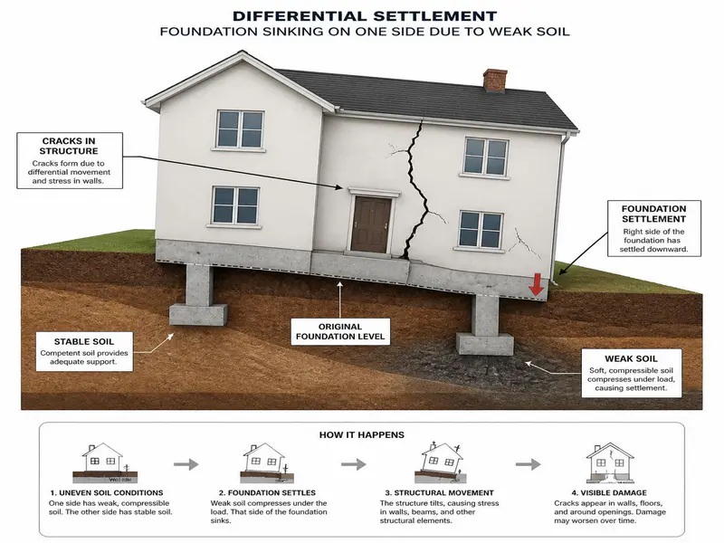
- Excessive Settlement: The soil compresses unevenly, leading to differential settlement. This manifests as cracked walls, jammed doors, broken plumbing lines, and structural collapse.
Ultimate vs. Safe Bearing Capacity
To design safely, engineers distinguish between three distinct terms:
- Ultimate Bearing Capacity (q_ult): The maximum gross pressure intensity at which the soil fails in shear.
- Net Bearing Capacity (q_net): The ultimate bearing capacity minus the weight of the soil that was excavated above the foundation level.
- Safe Bearing Capacity (SBC or q_safe): The maximum intensity of pressure that the soil can safely carry without any risk of shear failure. This introduces a Factor of Safety (FoS) to account for site uncertainties, soil variations, and unexpected environmental conditions.
Technical Overview of Soil Types and Typical SBC Values
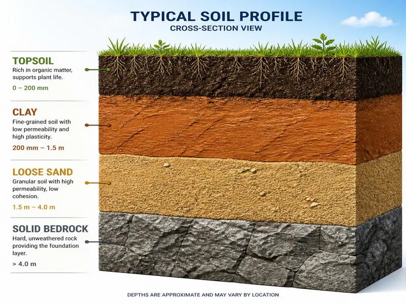
Different types of soil possess wildly different load-bearing characteristics. Before digging your foundation trenches, you must understand what lies beneath the topsoil. Below is a comprehensive engineering data table detailing typical Safe Bearing Capacity values across common soil types.
Comparative SBC Data Table
| Soil Classification / Type | Description & Characteristics | Typical Safe Bearing Capacity (SBC) in kg/cm² | Typical SBC in kN/m² (KiloNewtons per Sq. Meter) | Foundation Suitability & Engineering Notes |
|---|---|---|---|---|
| Hard Rock / Bedrock | Granite, basalt, limestone formations without fissures. | 32.5 to 33.0 | 3250 to 3300 | Excellent. Requires minimal footing width. No settlement risk. |
| Soft Rock | Shales, chalk, weathered sandstones. | 10.0 to 16.5 | 1000 to 1650 | Highly stable. Ideal for heavy residential configurations. |
| Coarse Sand / Gravel | Well-compacted, dense, coarse-grained soils. | 4.4 to 4.5 | 440 to 450 | Great stability. High permeability minimizes moisture retention. |
| Medium Dense Sand | Medium-grained, compacted particles. | 2.5 to 3.0 | 250 to 300 | Good for standard isolated footings. Requires adequate compaction. |
| Fine Sand / Loose Sand | Uniform fine grains, poorly compacted. | 1.0 to 1.5 | 100 to 150 | Moderate to low risk. Prone to liquefaction under water tables. |
| Soft Clay / Medium Clay | Cohesive soil with high plastic properties. | 1.0 to 1.5 | 100 to 150 | Poor. Highly prone to long-term consolidation settlement. |
| Black Cotton Soil | High plasticity clay containing Montmorillonite. | 0.5 to 0.7 | 50 to 70 | Highly hazardous. Swells when wet, shrinks dramatically when dry. |
| Peat / Organic Silt | Decomposed organic vegetation, spongy texture. | 0.0 to 0.5 | 0 to 50 | Unfit for direct foundation load. Requires deep piling or soil replacement. |
Core Mathematical Formulas for Soil Bearing Capacity
To calculate the structural dimensions of your foundation, you must use established geotechnical formulas. Karl von Terzaghi, the father of modern soil mechanics, formulated the definitive equations for bearing capacity.
1. Terzaghi’s Ultimate Bearing Capacity Equation (Strip Footing)
For a continuous or strip footing, the ultimate bearing capacity is expressed as:
text
q_ult = (c x Nc) + (gamma x D x Nq) + (0.5 x gamma x B x Ngamma)
Where:
- c = Cohesion of the soil (measured in kN/m² or kg/cm²)
- gamma = Effective unit weight of the soil (kN/m³ or kg/m³)
- D = Depth of the foundation from ground level (meters)
- B = Width of the footing (meters)
- Nc, Nq, Ngamma = Terzaghi’s dimensionless bearing capacity factors, which depend entirely on the soil’s internal angle of friction (phi).
2. Modifications for Footing Shapes
Residential buildings frequently use square or circular footings instead of strip footings. Terzaghi modified his equations as follows:
- Square Footings:
q_ult = (1.3 x c x Nc) + (gamma x D x Nq) + (0.4 x gamma x B x Ngamma) - Circular Footings:
q_ult = (1.3 x c x Nc) + (gamma x D x Nq) + (0.3 x gamma x B x Ngamma)
3. Safe Bearing Capacity (SBC) Formula
Once you have computed the ultimate or net bearing capacity, you apply a Factor of Safety (typically varying between 2.5 and 3.0 for residential structures) to find the working limits.
text
q_safe = Net Ultimate Bearing Capacity / Factor of Safety + (gamma x D)
For practical field approximations where net values merge with gross estimates safely, engineers routinely use:
SBC (q_safe) = q_ult / Factor of Safety
Before designing the footing, it is important to understand how footing size is calculated based on column load and soil strength. Read our detailed guide on Footing Size Calculation for Residential Building to learn the step-by-step method.
Practical Step-by-Step Calculation Examples
Let’s apply these formulas to real-world residential construction scenarios using clear, plain text math.
Example 1: Determining Foundation Footing Area via Known Soil SBC
Suppose you are designing a single-story residential building. The structural analysis shows that a specific column transfers a total dead load + live load of 300 kN to the base. A professional soil test report establishes the site’s Safe Bearing Capacity (SBC) as 150 kN/m². [1]
Step 1: Understand the core formula for pressure.
Pressure = Load / Area
Therefore, to stay within safe soil limits:
Required Footing Area = Total Load / Soil SBC
Step 2: Account for footing self-weight.
The concrete footing itself has massive weight. Engineers add a standard 10% safety margin to the column load to account for this.
Self-Weight Allowance = 300 kN x 10% = 30 kN
Total Structural Load = 300 kN + 30 kN = 330 kN
Step 3: Compute the minimum required surface area.
Required Area = 330 kN / 150 kN/m² = 2.2 Square Meters
Step 4: Determine physical footing dimensions.
If we opt for a square footing, the side length (B) is the square root of the required area:
Side Length (B) = Square Root of 2.2 = 1.48 meters
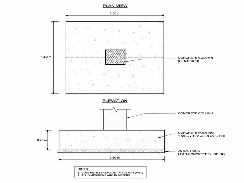
Site Recommendation: Round up to a practical field construction dimension of 1.5m x 1.5m square isolated footing.
Example 2: Concrete, Steel, and Material Volume Estimations
Now that we know our footing is 1.5m x 1.5m, let’s determine the concrete material quantities required for an engineered structural footing layout assuming a structural thickness of 400mm (0.4 meters).
Step 1: Calculate Total Wet Volume of Concrete Required.
Wet Volume = Length x Width x Thickness
Wet Volume = 1.5m x 1.5m x 0.4m = 0.9 Cubic Meters (m³)
Step 2: Convert Wet Volume to Dry Volume for Materials Batching.
Concrete shrinks when water is mixed with cement, sand, and aggregate. To compensate for this volume loss during hydration, engineers multiply the wet volume by a standard dry factor of 1.54.
Dry Volume Required = 0.9 m³ x 1.54 = 1.386 Cubic Meters
Step 3: Material Breakdown for M20 Grade Concrete (1 : 1.5 : 3 Ratio).
Most residential foundations use M20 grade concrete. The mix ratio is 1 part Cement, 1.5 parts Sand (Fine Aggregate), and 3 parts Crushed Stone (Coarse Aggregate).
text
Sum of Ratio Parts = 1 + 1.5 + 3 = 5.5
Cement Quantity Calculation:textCement Volume = (1 / 5.5) x 1.386 m³ = 0.252 Cubic Meters Use code with caution.Since 1 cubic meter of cement weighs approximately 1440 kg, and 1 bag equals 50 kg:textWeight of Cement = 0.252 m³ x 1440 kg/m³ = 362.88 kg Number of Cement Bags = 362.88 kg / 50 kg = 7.25 bags (Round up to 7.5 bags) Use code with caution.
- Sand (Fine Aggregate) Quantity Calculation:text
Sand Volume = (1.5 / 5.5) x 1.386 m³ = 0.378 Cubic MetersUse code with caution. - Coarse Aggregate Quantity Calculation:text
Aggregate Volume = (3 / 5.5) x 1.386 m³ = 0.756 Cubic MetersUse code with caution.
Foundation depth also depends on soil strength and soil conditions. Our guide on Minimum Depth of Foundation for Residential Building explains how engineers determine the correct depth for safe construction.
Unit Conversions Essential for Global Construction Sites
Construction practices vary by region. Site foremen, procurement managers, and engineers constantly translate metric designs into imperial measurements on local job sites. Use these standard calculations to convert raw volume quantities.
Key Volume and Mass Metric Conversions
- Cubic Meters (m³) to Cubic Feet (CFT):
Multiply by 35.3147
Example:0.378 m³ of sand x 35.3147 = 13.35 CFT - Cubic Meters (m³) to Brass:
In many South Asian construction environments, bulk aggregates are bought using the unit “Brass”.1 Brass = 100 Cubic Feet (CFT) = 2.8317 Cubic Meters (m³)
Multiply m³ by 0.3531 to find Brass volume values.
Example:0.756 m³ of aggregate x 0.3531 = 0.267 Brass - Kilograms to Metric Tons:
Divide the total mass weight value by 1000.
Example:3500 kg of structural reinforcement steel = 3.5 Metric Tons
On-Site Quality Control and Geotechnical Testing Methodologies
You should never guess your soil bearing capacity based on visual appearance alone. Professional builders deploy distinct field testing protocols to confirm geotechnical stability before pouring structural elements.
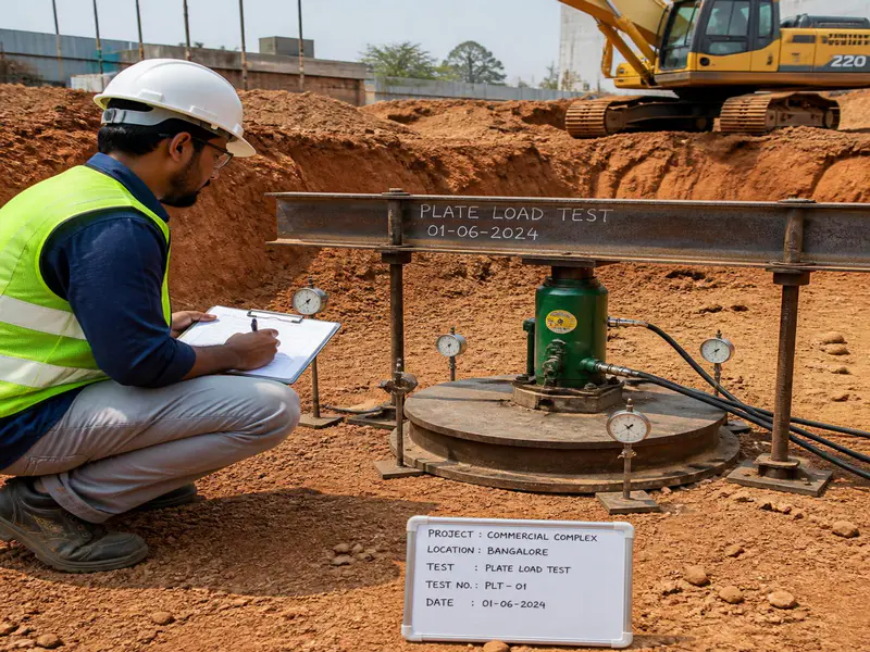
1. The Plate Load Test (IS: 1888 / ASTM D1194)
This is the most definitive on-site test for determining the ultimate bearing capacity of soils under a real-world load simulation.
- Methodology: A rigid steel test plate (typically 300mm to 750mm square) is placed at the proposed foundation pit depth level. A hydraulic jack applies progressive, increments of load against a heavy reaction frame beam setup.
- Observation: Settlement of the plate is carefully logged using high-precision dial gauges.
- Output: Engineers map a load-settlement curve to pinpoint exactly where the soil structure shifts from elastic behavior into shear failure.
2. Standard Penetration Test (SPT – IS: 2131 / ASTM D1586)
Highly popular for sand and fine gravelly deposits where digging wide pits for plate load tests is impractical.
- Methodology: A split-spoon sampler tube is driven into the bottom of a borehole using a standard 63.5 kg drop hammer falling from a height of 750mm.
- Observation: The engineer counts the number of hammer blows required to drive the sampler through three successive 150mm intervals.
- Output: The total number of blows for the final 300mm penetration is called the N-value. Geotechnical charts map this N-value directly to soil density, angle of internal friction, and estimated SBC.
3. Practical “Drop Weight” Field Approximation Method
If you are building a small structure in a remote location without immediate access to advanced hydraulic test rigs, you can use this traditional kinetic energy calculation to approximate safe soil bearing resistance:
- Procedure: Drop a heavy, known test weight mass (W, in kg) from a clear height (H, in centimeters) onto a steel pin or structural rod. Measure the depth of impression/penetration (d, in centimeters) into the soil bed layer.
- Approximate Ultimate Bearing Resistance Formula:text
Ultimate Resistance (R) = (W x H) / d SBC = (R / Area of Pin Base) / Factor of Safety (use 4.0 for manual field estimations)Use code with caution.
Caution: This manual drop-weight method is only a preliminary field check. Do not use it as a substitute for certified laboratory geotechnical test data when building multi-story or complex homes.
Foundation Strategies for Weak Soil Profiles
What happens if your site test returns a dangerously low soil bearing capacity? You have several engineering options to prevent building failure.
1. Excavation Depth Extension
Often, weak organic soils sit on top of much stronger geological formations. Simply digging deeper past the loose silt layers to place footings on a dense, underlying gravel or rock stratum can resolve the issue.
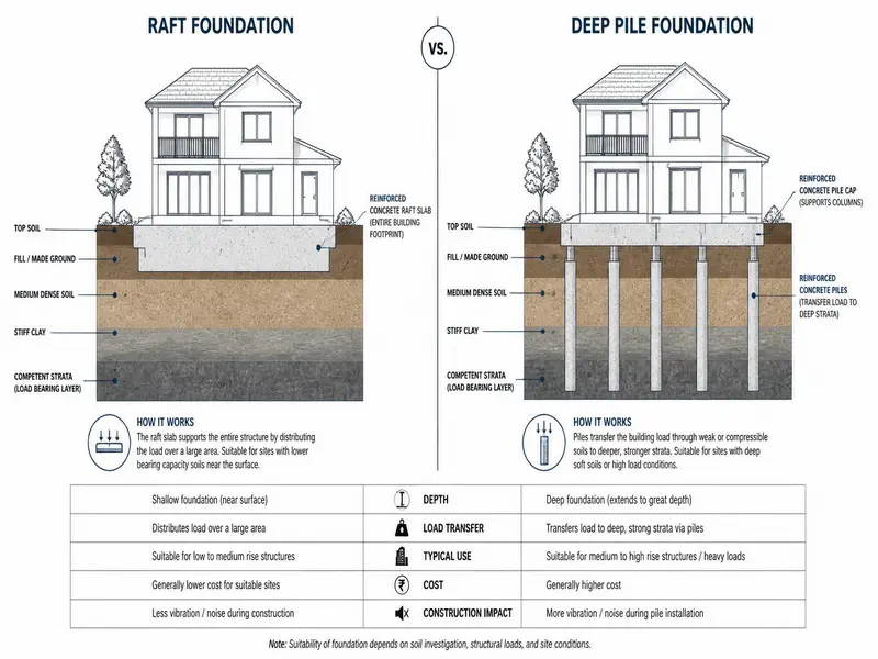
2. Broadening Footing Design (Raft or Mat Foundations)
If individual isolated column pads require massive surface areas that overlap, shift the architectural design to a full Raft Foundation. A raft foundation acts like a concrete boat hull, spreading the home’s total load across the entire footprint of the building. This reduces the structural pressure per square meter to a fraction of isolated designs.
3. Soil Compaction and Reinforcement
You can mechanically improve soil strength using heavy vibratory rollers, rammers, or manual compaction plates. For wet, cohesive clays, mixing in stabilizing additives like lime, fly ash, or ordinary Portland cement chemically modifies the clay matrix. This dramatically elevates the net safe bearing capacity.
4. Implementing Deep Pile Foundations
When building on deep expansive clays like Black Cotton Soil, shallow foundations fail because the soil shifts with the weather. Engineers bypass these unstable upper zones entirely by drilling deep Bored Cast-in-Situ Concrete Piles. These vertical columns transfer the house load via skin friction and end-bearing pressure down into deep, stable bedrock layers.
Site Quality Assurance and Material Wastage Control
Even the most accurate calculations will fail if poor site execution causes structural degradation. Follow these strict engineering guidelines during construction:
- Trench Bottom Compaction: Once excavation reaches the design depth, never pour concrete directly onto loose soil. Compact the bottom of the trench using mechanical rammers until it achieves at least 95% of its Maximum Dry Density (MDD).
- Mud Mat / Lean Concrete (PCC): Always pour a 50mm to 100mm thick layer of lean concrete (Plain Cement Concrete, typically M10 grade) at the bottom of the trench before placing steel reinforcement bars. This prevents soil from mixing into your structural footing concrete and protects reinforcement steel from groundwater corrosion.
- Water Table Management: If groundwater seeps into your foundation trenches, it dramatically lowers soil bearing capacity by creating upward pore water pressure. Use submersible dewatering pumps to keep the excavation dry until the concrete cures.
- Allowing for Material Wastage: When purchasing structural components, factor in standard on-site wastage parameters:
- Aggregate and Sand: Expect a 5% to 10% wastage factor due to handling loss, wind erosion, and mixing site spillage.
- Cement: Plan for a 2% wastage factor from handling and bag tearing.
- Reinforcement Steel: Budget a 3% to 5% wastage factor for cut-off scraps and lap lengths.
Frequently Asked Questions (FAQs) for SEO Features
1. What is the minimum depth of a foundation for a standard two-story house?
For a standard two-story residential building on normal soil, the minimum foundation depth should range between 1.0 to 1.5 meters (approx. 3.5 to 5 feet) below natural ground level. This depth ensures the footing sits below the topsoil layer and protects against seasonal volume changes caused by frost or drying cycles.
2. Can I build a house on soil with an SBC lower than 100 kN/m²?
Yes, but you cannot use standard isolated footings without risking severe settlement. For weak soils with an SBC between 50 and 100 kN/m² (like soft clay or loose sand), you must use either a Raft/Mat foundation to spread the load or implement soil stabilization techniques to increase the soil’s strength.
3. How does water accumulation affect the soil bearing capacity?
Water accumulation is highly detrimental. When soil becomes saturated, water fills the voids between particles, creating pore water pressure that pushes the soil grains apart. This can reduce the Safe Bearing Capacity of the soil by up to 50%, potentially leading to sudden foundation settlement or tilting.
4. What is the difference between safe bearing capacity and safe bearing pressure?
Safe Bearing Capacity (SBC) is based purely on preventing shear failure in the soil structure. Safe Bearing Pressure (SBP) is the maximum pressure that can be applied to the soil without causing excessive structural settlement (usually capped at 25mm for residential foundations). In soft soils, settlement controls the design, making Safe Bearing Pressure the limiting factor.
5. Why is Black Cotton Soil considered dangerous for house foundations?
Black Cotton Soil contains a high percentage of clay minerals like Montmorillonite. It expands dramatically when it absorbs water during monsoons and shrinks drastically, forming deep cracks, during hot summers. This constant swelling and shrinking exerts massive upward and downward pressure on footings, causing cracks throughout a house if it isn’t anchored by a deep pile foundation.
Engineering Toolbox provides useful engineering formulas, soil mechanics concepts, and technical data that help engineers understand soil properties and foundation design principles.
Conclusion
The structural integrity of your home relies on the soil bearing capacity beneath its foundation. Cutting corners on soil testing or structural design to save money can lead to expensive foundation repairs or structural failure down the road.
Before starting your build, invest in a professional geotechnical investigation. Work alongside a certified structural engineer to design footings that account for your site’s unique soil profile. Taking these proper engineering precautions ensures your home remains safe, level, and secure for a lifetime.
Shakeel T is a qualified Civil Engineer and Structural Consultant with extensive on-site experience in residential and commercial building construction. Specializing in material estimation, cost budgeting, and structural safety guidelines, he has successfully managed multiple real estate projects from foundation to finishing. Through this blog, Shakeel shares field-tested civil engineering thumb rules, IS Code practices, and practical site tips to help home builders execute their projects efficiently and within budget.
Education: Diploma in Civil Engineering
Expertise: Quantity Surveying, Material Estimation, Structural Design, and Site Management.