Introduction
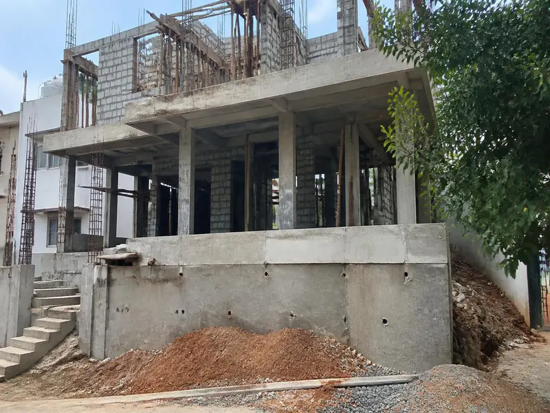
Building your dream home is a lifetime investment, and one of the most important structural decisions is selecting the correct Standard Plinth Height for House construction. While many homeowners focus mainly on interiors, premium flooring, and modular kitchens, experienced civil engineers understand that the real strength of a house begins from the foundation and the properly designed plinth level, which protects the building from dampness, flooding, and soil-related damage.
This comprehensive guide breaks down everything you need to know about the standard plinth height for a house, structural engineering guidelines, step-by-step volume calculations, and critical on-site quality checklists.
What is Plinth Height and Why Does It Matter?
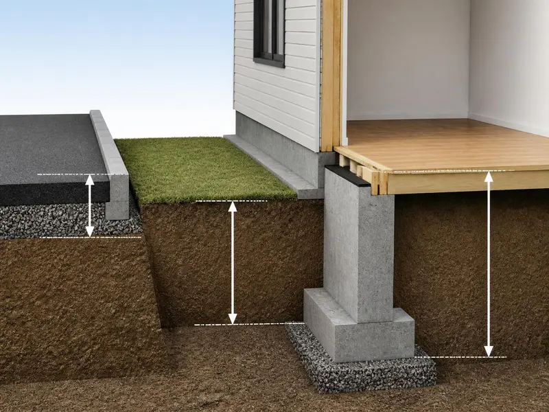
The plinth is the part of the superstructure located between the natural ground level (NGL) and the finished floor level (FFL) of the ground floor.
The plinth height is the vertical distance from the road level or natural ground level to the top surface of the ground floor slab.
       [ Finished Floor Level (FFL) ]  <-- Top of Plinth Beam / Slab

                     |
                     |  <-- Plinth Height (Standard: 450 mm to 600 mm)
                     |
_______[ Road Level / Natural Ground Level (NGL) ]_______
Critical Functions of a Plinth
- Prevents Water Ingress: It stops rainwater and surface runoff from entering your living spaces during heavy monsoon downpours.
- Resists Dampness: It acts as a barrier against capillary action, preventing moisture from rising into the brick walls from the soil below.
- Distributes Structural Load: The plinth beam binds all the columns together, distributing the superstructure’s load uniformly to the foundation.
- Accommodates Drainage: It creates a natural gravity slope for your kitchen, bathroom, and sewage pipes to connect smoothly to the municipal drainage line.
Foundation depth and plinth level are closely related in house construction. Read our guide on Minimum Depth of Foundation for Residential Building to understand how engineers determine safe foundation depth.
Standard Plinth Height for House in India
In Indian residential construction, the standard plinth height for a house is 450 mm to 600 mm (1.5 feet to 2 feet) from the adjacent road level.
However, this height is not a random choice. Under Indian Building Bye-Laws and National Building Code (NBC) guidelines, the plinth height must be tailored to specific site conditions.
| Site Condition | Recommended Plinth Height (Metric) | Recommended Plinth Height (Imperial) |
|---|---|---|
| Standard Level Road | 450 mm – 600 mm | 1.5 – 2.0 Feet |
| Low-Lying / Flood-Prone Area | 600 mm – 900 mm | 2.0 – 3.0 Feet |
| Hilly / Sloped Terrain | Variable (Minimum 600 mm at highest point) | Variable (Minimum 2.0 Feet) |
| Future Road Widening Areas | 750 mm – 1000 mm | 2.5 – 3.3 Feet |
Factors Dictating Plinth Height Selection
- Existing Road Level: Always measure from the highest point of the adjacent road, not the empty plot ground. Roads in India are regularly resurfaced by overlaying new asphalt or concrete, which raises the road level by several inches over a few years.
- High Flood Level (HFL): Research the last 20 to 30 years of flooding history in the locality. Your house FFL must be at least 300 mm above the highest recorded flood level.
- Municipal Drainage Invert Level: Your drainage pipes must drop down to the public sewer. If your plinth is too low, sewage will back up into your toilets.
Engineering Design of the Plinth Component
A robust plinth architecture consists of three interconnected layers:
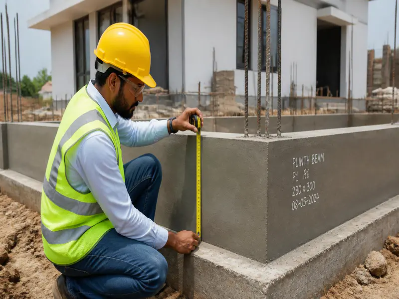
1. The Plinth Beam
A reinforced cement concrete (RCC) beam constructed at the ground level. It prevents differential settlement of columns and ties the structure together. For a standard residential building (G+1 or G+2), the standard plinth beam size is 230 mm x 300 mm or 230 mm x 450 mm.
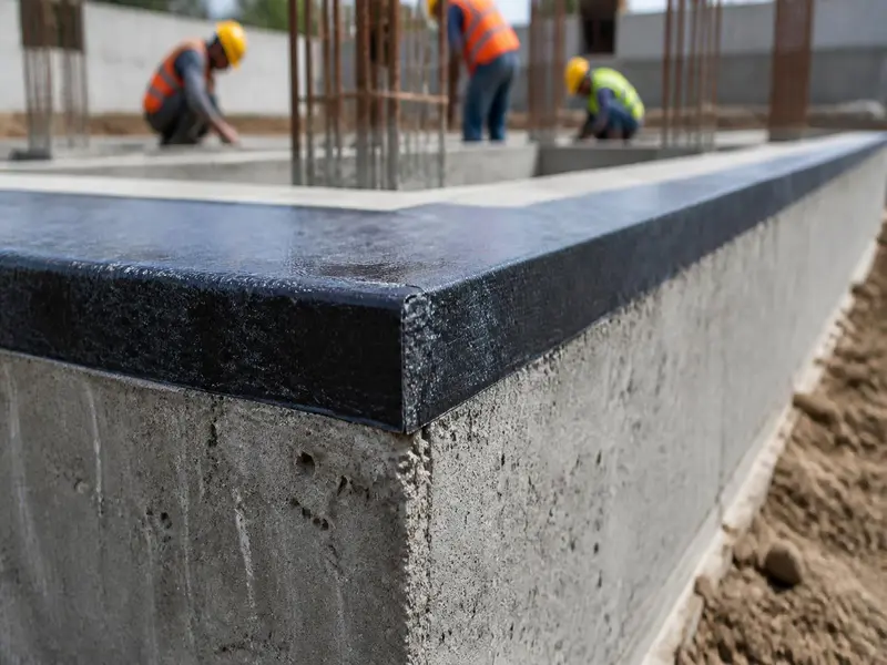
2. Plinth Masonry
The brickwork or stone masonry constructed above the foundation up to the plinth beam level. This encloses the soil matrix beneath the flooring.
3. Damp Proof Course (DPC)
A continuous layer of water-repellent material (usually 40 mm to 50 mm thick M15/M20 grade concrete mixed with waterproofing compounds like Dr. Fixit) applied over the plinth masonry or beam. It completely stops capillary water movement.
Core Civil Engineering Formulas for Plinth Material Estimation
To execute plinth filling and concrete works on-site, engineers use specific mathematical conversions to calculate raw material quantities.
1. Volume Calculation
- Total Volume = Length x Width x Thickness (or Height)
2. Dry Volume Estimation for Concrete
- Dry Volume of Concrete = Wet Volume x 1.54
(Note: 1.54 is the multiplication factor to account for the shrinkage of concrete elements when dry raw ingredients are mixed with water).
3. Dry Volume Estimation for Mortar (Brickwork)
- Dry Volume of Mortar = Wet Volume of Mortar x 1.33
4. Soil/Murrum Filling Compaction Factor
- Required Loose Soil Volume = Net Excavated Void Volume x 1.30
(Note: Loose soil shrinks by roughly 25% to 30% after watering and mechanical compaction).
Practical Step-by-Step Material Estimation Examples
Let us calculate the exact materials required for building a plinth system for a standard Indian home plot.
Scenario Profile
- Plot Size (Built-up Area): 10 meters x 12 meters (120 Square Meters / 1291 Sq. Ft.)
- Designed Plinth Height: 600 mm (0.6 meters)
Example 1: Soil / Murrum Backfilling Volume
Before casting the floor IPS, the hollow plinth perimeter must be filled with cohesive soil or murrum.
Step 1: Calculate the total wet volume of the plinth area
- Total Volume = Plot Length x Plot Width x Plinth Height
- Total Volume = 10 meters x 12 meters x 0.6 meters
- Total Volume = 72 Cubic Meters (m3)
Step 2: Deduct volume occupied by RCC Plinth Beams and Brickwork
- Let us assume the embedded beams and brick walls occupy roughly 15% of the total volume.
- Deductions = 72 x 0.15 = 10.8 Cubic Meters
- Net Internal Volume to Fill = 72 – 10.8 = 61.2 Cubic Meters
Step 3: Apply the Soil Compaction Factor
- Loose Soil Required = Net Internal Volume x 1.30
- Loose Soil Required = 61.2 x 1.30 = 79.56 Cubic Meters

Example 2: RCC Plinth Beam Material Calculation
Let us calculate the concrete and raw material quantities needed for casting the structural plinth beam running along the perimeter of our 10m x 12m plot.
Step 1: Calculate Total Beam Length
- Perimeter = 2 x (Length + Width)
- Perimeter = 2 x (10m + 12m) = 44 meters
- Let us assume internal cross-beams for partition walls add another 16 meters.
- Total Beam Length = 44m + 16m = 60 meters
Step 2: Calculate Wet Volume of Concrete
- Standard Beam Cross-Section = 230 mm x 300 mm (0.23m x 0.3m)
- Wet Volume = Total Length x Width x Depth
- Wet Volume = 60 meters x 0.23 meters x 0.30 meters
- Wet Volume = 4.14 Cubic Meters
Step 3: Calculate Dry Volume of Concrete
- Dry Volume = Wet Volume x 1.54
- Dry Volume = 4.14 x 1.54 = 6.375 Cubic Meters
Step 4: Mix Design Proportions (Using Standard M20 Grade – 1:1.5:3)
- Sum of Ratio Proportions = 1 (Cement) + 1.5 (Sand) + 3 (Aggregate) = 5.5
A. Cement Quantity Calculation
- Cement Volume = (1 / 5.5) x 6.375 = 1.159 Cubic Meters
- Since 1 Cubic Meter of Cement = 1440 kg, Total Weight = 1.159 x 1440 = 1668.96 kg
- Number of 50 kg Cement Bags = 1668.96 / 50 = 33.38 Bags (Say 34 Bags)
B. Fine Aggregate (Sand) Quantity Calculation
- Sand Volume = (1.5 / 5.5) x 6.375 = 1.738 Cubic Meters
C. Coarse Aggregate (Kapchi/Grit) Quantity Calculation
- Aggregate Volume = (3 / 5.5) x 6.375 = 3.477 Cubic Meters
Unit Conversions Matrix for Construction Management
Indian commercial markets source construction supplies using legacy systems alongside metric dimensions. Use this quick conversion table for material purchasing.
| From Unit | To Unit | Multiplication Factor | Real-World Application Reference |
|---|---|---|---|
| Cubic Meter (m3) | Cubic Feet (CFT) | 35.3147 | Used for buying sand, aggregates, and brass loads. |
| Cubic Meter (m3) | Brass | 0.3531 | 1 Brass equals exactly 100 Cubic Feet (CFT). |
| Cubic Meter (Cement) | Bags (50 kg) | 28.8 | Standard packing density calculation reference. |
| Metric Ton (Steel) | Kilograms (kg) | 1000.0 | Reinforcement bar weight check benchmarks. |
Practical Conversion Example
Convert the Sand volume from Example 2 (1.738 m3) into CFT and Brass for commercial ordering:
- Sand Volume in CFT = 1.738 x 35.3147 = 61.37 CFT
- Sand Volume in Brass = 61.37 / 100 = 0.613 Brass
Soil strength is an important factor for foundation design. You can read our guide on Soil Bearing Capacity for House Construction to understand how soil affects building stability.
Site Quality Controls, Execution Steps & Wastage Management
A master design can fail if site execution is poorly managed. Follow this step-by-step methodology during your plinth construction phase.
On-Site Execution Protocol
- Shuttering Quality Check: Ensure the side formwork for the plinth beam is perfectly vertical and supported by sturdy props. Wipe structural faces clean and apply shuttering oil before casting.
- Clear Cover Maintenance: Use manufactured concrete cover blocks of exactly 25 mm thickness under and beside the steel reinforcement cages. This prevents the steel bars from rusting over time.
- Compaction Mechanics: Never allow the pouring team to add excess water to make concrete flow easily. Use mechanical needle vibrators (40mm pin) to eliminate internal air pockets.
- Layered Backfilling: Fill soil inside the plinth in layers not exceeding 150 mm to 200 mm at a time. Ram each layer with manual or mechanical compactors while adding water to reach maximum dry density. Failing to do this causes your expensive floor tiles to crack and sink later.
Material Wastage Factors Matrix
Always order materials including allowance for structural waste, cutting loss, and transport handling:
- RCC Structural Concrete: Add 2% to 3% wastage allowance.
- Reinforcement Steel (Rebar cutting): Add 4% to 5% scrap allowance.
- Brickwork/Blockwork Masonry: Add 5% breakage allowance.
- Soil/Murrum Fill Material: Add 25% to 30% volume compaction shrinkage allowance.
Frequently Asked Questions (FAQs)
1. What happens if the plinth height is kept lower than the road level?
If your plinth sits below the road level, surface rainwater during storms will run straight into your home. Additionally, as municipal bodies raise the road level during maintenance cycles, your home will sink into a low-lying pocket, causing severe dampness and sewage backup issues.
2. Can I build a residential building without a plinth beam?
No, building without a plinth beam is highly dangerous, especially in areas with expansive soils like Black Cotton soil. The plinth beam functions as a continuous structural tie that binds columns together, neutralizes differential settlement, and protects the brick walls from seismic cracks.
3. What is the difference between plinth level and sill level?
The plinth level is the foundational floor level of your rooms (where you walk). The sill level is the intermediate height above the floor level where the bottom base of a window frame rests (typically 900 mm or 3 feet above the plinth level).
4. Is it mandatory to install a Damp Proof Course (DPC) if I have a plinth beam?
Yes, a DPC is highly recommended even with an RCC plinth beam. Micro-cracks or pores within regular concrete can still allow subsoil moisture to rise up walls via capillary action. A dedicated 40mm thick DPC layer treated with waterproofing additives acts as a definitive barrier.
5. Which soil is best suited for backfilling the plinth cavity?
Murrum (lateritic red soil) or non-expansive structural sand is ideal for plinth filling. Avoid using expansive clayey soils, black cotton soil, or topsoil containing organic matter, as they swell up when wet and shrink when dry, which can crack your flooring.
The Bureau of Indian Standards provides official building codes and construction guidelines used across India.
Conclusion
Determining the ideal standard plinth height for a house is a critical decision that balances civil engineering rules with future infrastructure realities. Setting your plinth height between 450 mm and 600 mm above the highest point of the adjacent road protects your building from water logging, dampness, and structural vulnerability.
Ensure that you calculate your volumes accurately using dry correction factors, account for material compaction margins, and use a dedicated DPC layer on-site to keep your structure safe and dry for decades to come.
Shakeel T is a qualified Civil Engineer and Structural Consultant with extensive on-site experience in residential and commercial building construction. Specializing in material estimation, cost budgeting, and structural safety guidelines, he has successfully managed multiple real estate projects from foundation to finishing. Through this blog, Shakeel shares field-tested civil engineering thumb rules, IS Code practices, and practical site tips to help home builders execute their projects efficiently and within budget.
Education: Diploma in Civil Engineering
Expertise: Quantity Surveying, Material Estimation, Structural Design, and Site Management.