Introducation
In structural engineering and modern building development, structural stability relies entirely on how effectively individual load-bearing components are interconnected. A building with robust columns and deep foundations can still fail during seismic shifts or differential soil settlement if its vertical members act completely independently. This is where the integration of a Tie Beam in Construction becomes critical.
A tie beam acts as a continuous horizontal structural tie that binds columns, rafters, or foundations together. This ensures the entire building acts as a single cohesive unit when subjected to external forces.
This comprehensive, field-tested guide provides everything you need to know about tie beams. You will learn their primary structural purposes, standard architectural dimensions, structural steel reinforcement designs, and practical step-by-step material estimation calculations.

Why Tie Beams Matter
From a structural engineering standpoint, a tie beam is primarily a tension member, though it can also resist compression and minor bending stresses depending on its location. Unlike a plinth beam or a grade beam which transfer heavy floor slab loads directly to the underlying soil a tie beam is primarily designed to counteract horizontal forces and maintain structural alignment.
If a building lacks properly engineered tie beams, it is highly vulnerable to several types of structural damage:
1. Differential Settlement Mitigation
Soils are rarely perfectly uniform across an entire construction footprint. One corner of a building might sit on dense, compacted clay, while another rests on loose, sandy loam. Over time, the heavier side of the building may sink deeper than the other. Without horizontal tie beams to distribute these structural movements evenly between columns, this differential settlement causes severe diagonal cracks to tear through masonry walls and can ultimately lead to a partial or total collapse of the building framework.
2. Seismic and Lateral Force Resistance
During earthquake events or high-velocity wind storms, buildings are subjected to intense lateral (horizontal) forces. These forces try to push the columns away from one another, causing a structural failure known as column splaying. A tie beam mechanically clamps the columns together. This forces the entire framework to sway uniformly, which absorbs and dissipates the seismic energy safely down into the foundation grid.
Column design is essential for structural stability. Read our detailed guide oncolumn size for 1, 2 and 3 storey buildings.
Primary Purposes and Functions of a Tie Beam
To fully understand its application on an active job site, let us break down the primary engineering functions of a tie beam:
- Eliminating Column Displacement: It mechanically prevents columns from moving outward or shifting laterally when subjected to heavy vertical roof loads.
- Reducing Slenderness Ratio: By tying long, unbraced vertical columns at an intermediate height, it effectively reduces their slenderness ratio, which dramatically increases the load-carrying capacity of the column.
- Supporting Upper-Level Masonry: In multi-story buildings, intermediate tie beams provide a stable, level horizontal base to support interior partition walls, preventing wall sagging.
- Tying Roof Trusses: In industrial steel sheds or wooden roof construction, tie beams connect the lower ends of rafters, preventing the weight of the roof from pushing the load-bearing side walls outward.
Standard Dimensions and Sizes of Tie Beams
The physical size of a tie beam is determined by the clear span distance between the columns it connects and the magnitude of the lateral forces it is expected to resist. However, residential and commercial projects follow standard industry benchmarks during the structural design phase:
Residential Buildings (G+1 to G+2 Floors)
- Minimum Width: 230 mm (9 inches) – This matches the standard thickness of external brick masonry walls for seamless plastering.
- Minimum Depth: 230 mm to 300 mm (9 to 12 inches).
- Standard Cross-Section Size: 230 mm x 230 mm or 230 mm x 300 mm.
Commercial and Industrial Structures
- Minimum Width: 300 mm to 450 mm (12 to 18 inches).
- Minimum Depth: 450 mm to 600 mm (18 to 24 inches).
Simple Rule-of-Thumb for Preliminary Sizing
For quick site verification before structural structural checks, engineers use a basic span-to-depth ratio rule:
- Tie Beam Depth = Clear Span Distance / 16
- Example: If the distance between two columns is 4.8 meters (4800 mm), the preliminary estimated depth of the tie beam should be: 4800 / 16 = 300 mm.
Reinforcement Guide: Steel Bars and Stirrups
Because concrete has incredibly high compressive strength but is weak under tension, steel reinforcement bars must be cast inside the tie beam to handle the pull and sway forces.
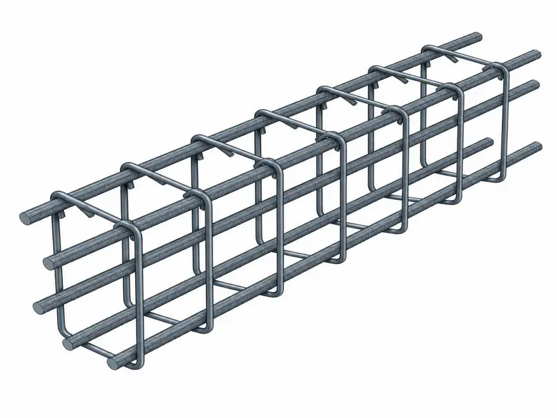
1. Main Longitudinal Bars (Top and Bottom Reinforcement)
- Minimum Bar Diameter: Never use steel bars thinner than 12 mm for the main longitudinal reinforcement in a tie beam.
- Minimum Quantity: A minimum of 4 continuous longitudinal bars must be used (2 bars at the top and 2 bars at the bottom of the steel cage).
- Steel Grade: High-Yield Strength Deformed bars (such as TMT Fe 500 or Fe 550) are standard to ensure excellent bonding with concrete.
2. Shear Reinforcement (Stirrups / Lateral Ties)
Stirrups keep the main longitudinal steel bars perfectly aligned during the concrete pour and resist diagonal shear stresses near the column joints.
- Minimum Stirrup Bar Diameter: 8 mm.
- Standard Stirrup Spacing: 100 mm center-to-center near the column joints (where shear stress peaks) and increasing to 150 mm to 200 mm center-to-center toward the middle of the beam span.
- Hook Bend Angle: Stirrup hooks must always be bent at a strict 135-degree angle with a minimum hook length of 75 mm to prevent the steel cage from bursting apart during an earthquake.
3. Clear Concrete Cover
To protect the internal steel bars from moisture, carbonation, and eventual rusting, a clear concrete cover must be maintained using plastic or concrete spacer blocks:
- Standard Clear Cover for Tie Beams: 25 mm to 30 mm.
Step-by-Step Material Estimation Calculations
Let us walk through a real-world engineering calculation to find the exact volume of concrete and the total weight of steel reinforcement required to cast a tie beam on a job site.
Project Specifications:
- Total Continuous Beam Length: 12.0 meters
- Tie Beam Width: 0.23 meters (230 mm)
- Tie Beam Depth: 0.30 meters (300 mm)
- Concrete Mix Design Grade: M20 Grade (Nominal Volumetric Ratio = 1 : 1.5 : 3)
- Main Top Reinforcement: 2 bars of 12 mm diameter
- Main Bottom Reinforcement: 2 bars of 16 mm diameter
- Stirrups: 8 mm diameter bars spaced at 150 mm center-to-center
- Clear Concrete Cover: 25 mm (0.025 meters)
Part A: Concrete Volume Calculation
Step 1: Calculate the Finished Wet Volume of Concrete
Multiply the physical geometric dimensions of the beam:
- Wet Volume = Length x Width x Depth
- Wet Volume = 12.0 x 0.23 x 0.30 = 0.828 cubic meters (m3)
Step 2: Convert Wet Volume to Total Required Dry Volume
When dry cement, sand, and stone aggregate are mixed with water, the mix shrinks as fine particles fill the internal voids. To compensate, multiply the wet volume by the standard concrete safety multiplier factor of 1.54:
- Dry Volume = Wet Volume x 1.54
- Dry Volume = 0.828 x 1.54 = 1.275 cubic meters (m3)
Step 3: Extract Sand and Aggregate Components for M20 Mix
- Sum of Mix Ratio Parts = 1 (Cement) + 1.5 (Sand) + 3 (Aggregate) = 5.5
- Volume of Sand Required = (1.5 / 5.5) x 1.275 = 0.348 cubic meters (m3)
- Volume of Coarse Aggregate Required = (3 / 5.5) x 1.275 = 0.695 cubic meters (m3)
Part B: Steel Reinforcement Weight Calculation
To calculate the weight of steel, we use the standard engineering weight-per-meter formula:
- Weight of Steel Bar per Meter = (D x D) / 162 (where D is the bar diameter in millimeters).
Step 1: Calculate Weight of Top Main Bars (2 Bars of 12 mm)
- Total Length of Top Bars = 2 bars x 12.0 meters = 24.0 meters
- Weight per Meter of 12mm Bar = (12 x 12) / 162 = 0.888 kg/m
- Total Weight of Top Bars = 24.0 meters x 0.888 kg/m = 21.31 kg
Step 2: Calculate Weight of Bottom Main Bars (2 Bars of 16 mm)
- Total Length of Bottom Bars = 2 bars x 12.0 meters = 24.0 meters
- Weight per Meter of 16mm Bar = (16 x 16) / 162 = 1.580 kg/m
- Total Weight of Bottom Bars = 24.0 meters x 1.580 kg/m = 37.92 kg
Step 3: Calculate the Number of Stirrups Required
- Number of Stirrups = (Total Beam Length / Stirrup Spacing) + 1
- Number of Stirrups = (12.0 meters / 0.150 meters) + 1 = 80 + 1 = 81 Stirrups
Step 4: Calculate the Cutting Length of a Single Stirrup
Subtract the 25 mm concrete cover from all four sides of the beam dimensions to find the stirrup profile:
- Stirrup Width (a) = 230 mm – 25 mm – 25 mm = 180 mm = 0.18 meters
- Stirrup Depth (b) = 300 mm – 25 mm – 25 mm = 250 mm = 0.25 meters
- Cutting Length = 2 x (a + b) + Hook Length Allowance
- Hook Length Allowance (for two 135-degree hooks) = 2 x (10 x Stirrup Diameter) = 2 x 10 x 8 mm = 160 mm = 0.16 meters
- Total Cutting Length of 1 Stirrup = 2 x (0.18 + 0.25) + 0.16 = 2 x (0.43) + 0.16 = 0.86 + 0.16 = 1.02 meters
Step 5: Calculate Total Weight of Stirrups (8 mm Bars)
- Total Length of 8mm Steel for Stirrups = 81 stirrups x 1.02 meters = 82.62 meters
- Weight per Meter of 8mm Bar = (8 x 8) / 162 = 0.395 kg/m
- Total Weight of Stirrups = 82.62 meters x 0.395 kg/m = 32.64 kg
Understanding plinth beams is important because they also connect structural elements at the ground level. Read our guide on plinth beam in construction to learn about its purpose and reinforcement details.
Transforming Material Volume into Commercial Market Units
Material yards and commercial suppliers do not bill construction products in pure cubic meters or kilograms. Below is the complete, converted structural procurement matrix for your 12-meter tie beam order:
Unit Transformation Constants:
- 1 Cubic Meter (m3) = 35.3147 Cubic Feet (CFT)
- 1 Metric Ton = 1000 Kilograms (kg)
- Average Compacted Bulk Density of Sand = 1600 kg/m3
Complete Commercial Material Order Matrix
| Material Component | Pure Calculated Value | Volume in Cubic Feet (CFT) | Weight in Metric Tons / Kilograms | Final Commercial Order Quantity (With 5% Wastage Included) |
|---|---|---|---|---|
| Concrete (Total Wet) | 0.828 m3 | 29.24 CFT | – | 0.87 m3 Ordered |
| Construction Sand | 0.348 m3 | 12.29 CFT | 0.556 Tons (556 kg) | 13.0 CFT Ordered |
| Coarse Aggregate | 0.695 m3 | 24.54 CFT | 1.112 Tons (1112 kg) | 26.0 CFT Ordered |
| Main Steel Bars (12mm) | 24.0 meters | – | 21.31 kg | 22.50 kg Ordered |
| Main Steel Bars (16mm) | 24.0 meters | – | 37.92 kg | 40.00 kg Ordered |
| Stirrup Steel Bars (8mm) | 82.62 meters | – | 32.64 kg | 34.50 kg Ordered |
On-Site Quality Control Framework and Field Precautions
To guarantee that the structural tie beams perform exactly as engineered, site supervisors must enforce strict quality control checks before, during, and after the concrete pour:
1. Formwork and Alignment Inspection
- Ensure that the timber wooden planks or steel plates used for formwork are perfectly level, completely watertight, and robustly braced.
- Apply a generous layer of form-release oil to the inner surfaces before placing reinforcement. This prevents the formwork from absorbing moisture from the fresh concrete and ensures a smooth finish when dismantled.
2. Lap Splice Positioning Controls
- Steel bars come in standard lengths of 12 meters. If your tie beam runs longer than that, you must lap two bars together.
- The Golden Rule: Never lap all steel reinforcement bars at the exact same cross-section profile. Stagger the lap splices.
- The lap length for tie beams must follow a minimum specification of 50D (50 times the bar diameter). For a 12 mm bar, the overlapping zone must be at least: 50 x 12 mm = 600 mm.
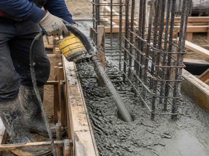
3. Honeycombing Prevention and Compaction
- Because tie beams have narrow cross-sections tightly packed with steel cages, fresh concrete can easily get jammed, creating hollow structural air pockets known as honeycombing.
- Always utilize a mechanical needle vibrator (40 mm or 25 mm nozzle depending on bar spacing) to settle the fresh concrete completely around the steel cage. Never over-vibrate, as this causes segregation—where heavy stones sink to the bottom and weak cement slurry rises to the top.
4. Curing Duration Mandate
- Do not remove the vertical side formwork boards for at least 24 to 48 hours after casting.
- Once the forms are stripped, wrap the tie beam in damp hessian/jute bags and keep them continuously saturated with clean water for a minimum of 7 to 10 consecutive days. Proper curing allows the concrete to develop its full structural design compressive strength.
Frequently Asked Questions (FAQs)
Q1: What is the main difference between a tie beam and a plinth beam?
A plinth beam is constructed at ground level or slightly above ground level to support the weight of the brick walls and the interior floor slab, transferring these heavy vertical loads to the foundation. A tie beam can be built at any intermediate height of a structure and is primarily designed to prevent columns from splaying outward under lateral tension.
Q2: Can a tie beam be eliminated to reduce building material costs?
No. Eliminating tie beams in structures built on soft soil or in high-risk seismic zones compromises structural safety. Without tie beams, columns act independently, making the building highly vulnerable to cracks from differential soil settlement or collapse from earthquake movements.
Q3: What concrete mix grade is recommended for casting tie beams?
The minimum structural grade of concrete recommended for casting reinforced tie beams is M20 Grade (1 part cement : 1.5 parts sand : 3 parts stone aggregate) for standard residential structures, and M25 or M30 Grade for high-rise commercial frameworks.
Q4: Why are stirrups spaced closer together near column joints?
When a building experiences lateral loads, the shear stress peaks at the column-beam intersections. Spacing stirrups closer together (e.g., 100 mm center-to-center) near these joint areas provides localized shear resistance and prevents structural cracking where stress concentrations are highest.
Q5: Is a tie beam necessary if the foundation is anchored in hard rock?
Yes. While hard rock eliminates the risk of differential soil settlement, tie beams remain critical for multi-story framing to reduce the effective slenderness ratio of long vertical columns and to provide uniform lateral stability against high winds and seismic shocks.
Engineering Toolbox provides useful engineering formulas, technical explanations, and construction material information used by civil engineers worldwide.
Conclusion
Integrating a properly engineered Tie Beam in Construction is an essential technical requirement to ensure your building acts as a single, structurally secure unit. By mechanically tying vertical columns together, tie beams mitigate the severe threats of differential soil settlement and provide vital resistance against lateral seismic forces.
Achieving structural safety requires careful attention to detail at every step: choosing the right cross-sectional dimensions, detailing the steel cages with 135-degree stirrup hooks, and executing accurate concrete material estimations. Prioritizing these engineering principles on-site ensures your construction project remains structurally sound and highly durable for decades to come.
Shakeel T is a qualified Civil Engineer and Structural Consultant with extensive on-site experience in residential and commercial building construction. Specializing in material estimation, cost budgeting, and structural safety guidelines, he has successfully managed multiple real estate projects from foundation to finishing. Through this blog, Shakeel shares field-tested civil engineering thumb rules, IS Code practices, and practical site tips to help home builders execute their projects efficiently and within budget.
Education: Diploma in Civil Engineering
Expertise: Quantity Surveying, Material Estimation, Structural Design, and Site Management.
After looking over a number of the articles on your web site, I
truly like your technique of blogging. I added it to my bookmark website list and will be
checking back in the near future. Please visit my web site as well and let me know your opinion.